

Infrared-transmitting cover
A technology of infrared transmission and infrared signals, which is applied in the fields of optics, instruments, short-distance systems, etc.
- Summary
- Abstract
- Description
- Claims
- Application Information
AI Technical Summary
Problems solved by technology
Method used
Image

Examples
no. 1 approach
[0071] Below, refer to Figure 5 , the infrared transmission cover 21 related to the first embodiment of the present invention will be described.
[0072] The portable information terminal 22 as an electronic device has a transmitter and receiver for transmitting and exchanging information between other electronic devices without cables using infrared signals (for example, infrared rays with a wavelength around 850nm). Infrared communication, for example, is generally performed in accordance with the Infra-red Data Access (IrDA: Infra-red Data Access) standard. The cover 21 closes an opening (infrared signal interface) 22 a formed in the casing of the portable information terminal 22 . Figure 5 The lower side is the outer side of the cover 21 and each layer, and the upper side is the inner side of the cover 21 and each layer.
[0073] The cover 21 includes an infrared transmissive base layer 23 and a dielectric multilayer film 24 formed on the outer surface of the base laye...
Embodiment 1
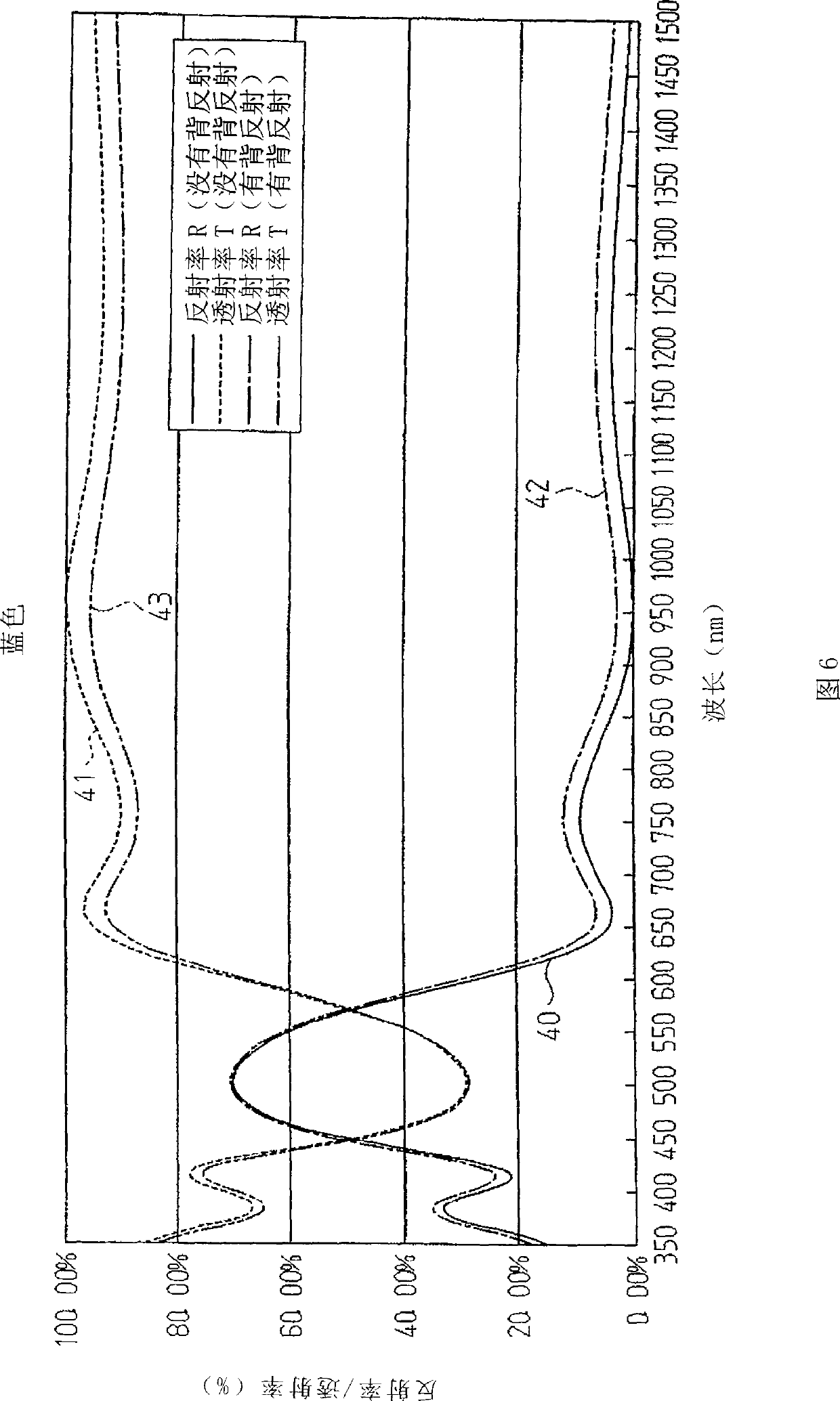
[0093] now refer to Figure 6 , Figure 7 , Table 1 and Table 2, illustrate the cover of Example 1.
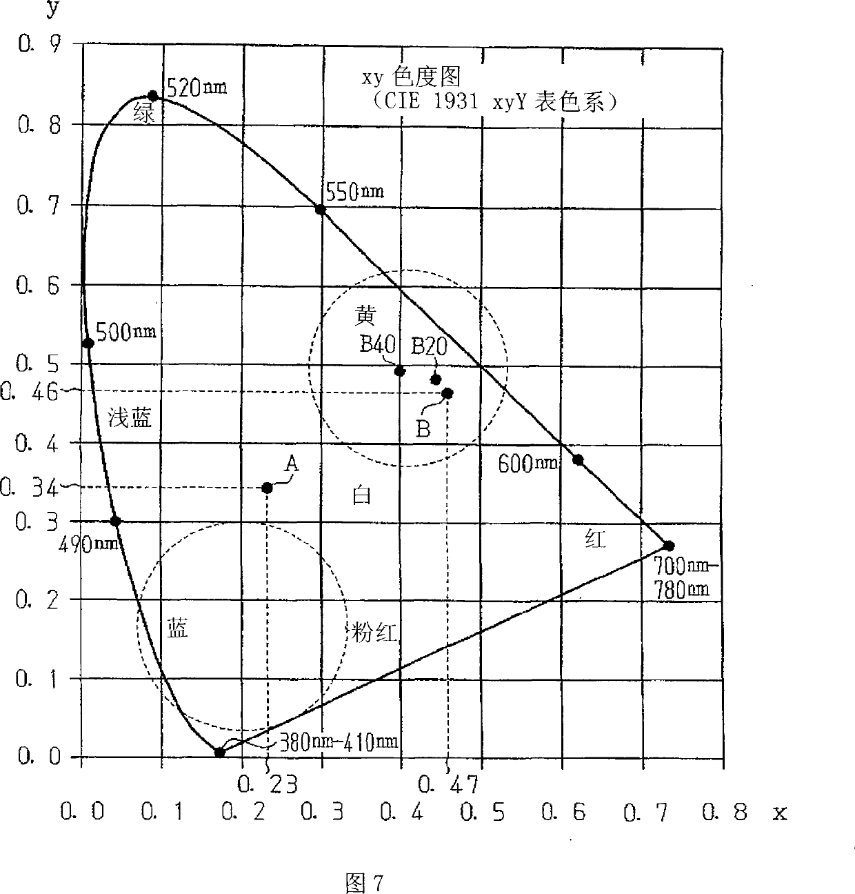
[0094] The lid of Example 1, with Figure 5 The illustrated cover 21 has the same layer structure, including an acrylic resin base layer 23 and a dielectric multilayer film 24 that is transparent to infrared rays and reflects blue light. The dielectric multilayer film 24 is composed of eight thin film layers alternately laminating high-refractive-index material (ZrO2) and low-refractive-index material (SiO2) on the outer surface of the acrylic resin base layer 23. The dielectric multilayer film 24 reflects light having a central wavelength λc. The central wavelength λc is related to the color of the reflected light, ie to the color of the cover. The eight layers constituting the dielectric multilayer film 24 of Embodiment 1 are designed to reflect light having a central wavelength λc of 495 nm, that is, to reflect blue light.
[0095] Table 1
[0096] Example 1: Blue ref...
Embodiment 2
[0108] The lid of Example 2 has the same Figure 5 The cover 21 has the same structure as the cover 21, and includes a base layer 23 made of acrylic resin and a dielectric multilayer film 24 that reflects yellow light. The dielectric multilayer film 24 is composed of seven thin film layers in which high refractive index material (ZrO2) and low refractive index material (SiO2) are alternately laminated. The center wavelength λc of the dielectric multilayer film 24 is the wavelength (600 nm) of the yellow reflected light.
[0109] The spectral reflection characteristics and the spectral reflection characteristics of the dielectric multilayer film 24 in embodiment 2 are as follows Figure 8 shown. exist Figure 8 , the curve 50 represents the spectral reflection characteristic (reflectance R) in the case of "no back reflection". Curve 51 represents the spectral transmission characteristic (transmittance T) in the case of "no back reflection". Curve 52 represents the spectral...
PUM
 Abstract
Description
Claims
Application Information