Light source lighting device

A technology for lighting devices and light sources, which is applied to lighting devices, light sources, cooling/heating devices of lighting devices, etc., can solve the problems of insufficient heat dissipation of LEDs and relatively high working environment requirements, and achieves good light output effect and heat dissipation. Good results

A technology for lighting devices and light sources, which is applied to lighting devices, light sources, cooling/heating devices of lighting devices, etc., can solve the problems of insufficient heat dissipation of LEDs and relatively high working environment requirements, and achieves good light output effect and heat dissipation. Good results

CN101078470AInactive Publication Date: 2007-11-28南京淳鑫源电子科技有限公司

Image

  • Light source lighting device
  • Light source lighting device
  • Light source lighting device

Examples


Embodiment Construction

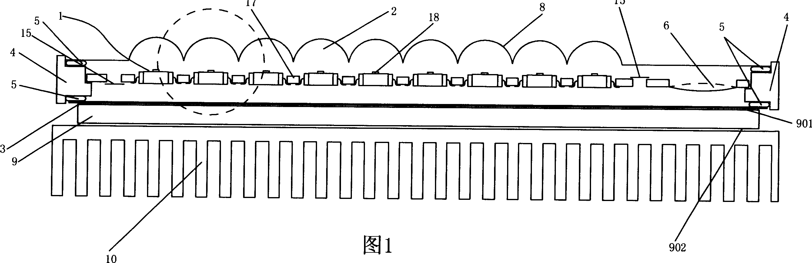
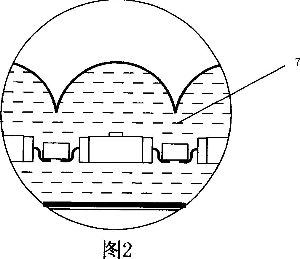
[0036] As shown in Figure 1, it is a schematic structural diagram of the first embodiment of the light source lighting device of the present invention, and the specific structure of this embodiment is described in conjunction with the partial enlarged view of Figure 1 shown in Figure 2, the light source illuminator includes an LED array 1, in In this embodiment, a plurality of LED chips 18 in the LED array 1 are installed together through the PCB board 17 , the light-transmitting device adopts the lens housing 8 , and the cooling liquid 7 is filled in the lens housing 8 to form a liquid lens together. The lens array cooperates with the LED array 1 for emitting the light emitted by the LED array 1 in a parallel or divergent manner. The periphery of the lens array and the heat conducting plate 3 is provided with a sealing base 4, and a sealing gasket 5 is provided at the sealing base 4 to form a sealed container, and the LED array 1 is sealed between the sealed container formed b...


PUM


Abstract

The invention relates to a lighting equipment of light source, comprising an illuminator of light source, characterized in that the illuminator of light source comprising LED array; the LED array is set in the sealing container; light conducting device assembled with the LED array for conducting light of LED array out is set on the sealing container; transparent cooling liquid for cooling the LED array is filled in the sealing container; and heat conducting device for conducting heat quantity of said cooling liquid out is set on the sealing device. Because cooling liquid is added in the LED chip in said lighting equipment of light source, heat dispersion of LED chip is better and light conducting device is set so that the effect of light extraction is very good.

Description

technical field [0001] The present invention relates to a light source device, and more particularly, to a projector with the light source device. Background technique [0002] Traditional projectors have always used halogen lamps and high-pressure mercury lamps as their light sources. These light sources have their limitations. The life of the halogen lamp is short, and the high-pressure mercury lamp requires a high-voltage power circuit, which makes the projector large and heavy. This hinders the small size and light weight of the projector. Although the lifespan of a high-pressure mercury lamp is longer than that of a halogen lamp, it is still short-lived, and it takes a long time to start. As a new light source, LED is small in size and light in weight, and has many advantages, but it has relatively high requirements on the working environment, especially on temperature, and the existing technology cannot solve the problem of LED heat dissipation well. Contents of the...

Claims


Application Information

Patent Timeline
28 Nov 2007
Publication
CN101078470A
IPC
F21S4/00; F21V29/00; F21V8/00; F21S4/28; F21V29/508; F21V29/56; F21Y115/10
Inventors
曹嘉灿