

Optics and manufacturing method of led car high beam combination lamp
A technology of LED light source and combination lamp, which is applied in the direction of semiconductor devices, light sources, electric light sources, etc. of light-emitting elements, can solve the problems of complex structure and cost a lot of money, and achieve the effects of good light efficiency, saving manufacturing costs, and wide application range
- Summary
- Abstract
- Description
- Claims
- Application Information
AI Technical Summary
Problems solved by technology
Method used
Image

Examples
Embodiment 1
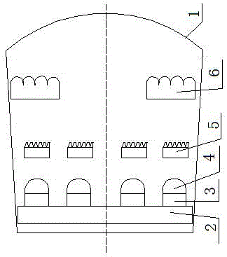
[0023] An LED car high beam combination lamp, which comprises: a high beam combination lamp housing 1, an aluminum-based PCB board 2 is housed in the high-beam combination lamp housing, and the aluminum-based PCB board is connected to a white LED light source group 3. The white LED light source group is connected to the infrared LED light source group 4, a Fresnel lens group 5 is installed in front of the infrared LED light source group, and a fly-eye lens group 6 is installed in front of the Fresnel lens group.
[0024] In the LED car high beam combination lamp, the white LED light source in the white LED light source group has a light emitting angle of 30-80 degrees, and the infrared LED light source in the infrared LED light source group has a light emission angle of 30-80 degrees Angle, the diffusion angle of the fly-eye lens in the fly-eye lens group is ±45 degrees.
Embodiment 2
[0026] An optical method for an LED car high beam combination lamp, the white LED light source group and the infrared LED light source group are arranged on a square dot matrix aluminum-based PCB board, and the aluminum-based PCB board is placed at the focal position of the Fresnel lens group, The light emitted by the LED in the middle position passes through the corresponding Fresnel lens array in front of it to generate a collimated beam to form the light distribution of the high beam of the car. The surrounding white LED light source groups and infrared LED light source groups are arranged alternately. The lens group forms a collimated light beam, and then forms the light distribution of the car daytime running lights and the auxiliary light distribution of infrared night vision through the fly eye lens group.
Embodiment 3
[0028] A manufacturing method of LED automobile high-beam combination lights, welding or bonding white LED light source groups and infrared LED light source groups on an aluminum-based PCB to form a light source lattice, and clamping a Fresnel lens group on the light source as the focal point Install the fly-eye lens group in the coaxial position where daytime running lights and night vision auxiliary light distribution are required.
PUM
 Abstract
Description
Claims
Application Information