
Knee prosthesis with extended range of motion

a knee joint and extended range technology, applied in the field of knee joint replacement with knee prosthesis, can solve the problems of excessive wear of the tibial component, the knee is distracted, and the knee is not able to accurately rotate about the longitudinal axis, so as to achieve increased hypertension, wide range of motion, and increased hypertension

Active Publication Date: 2006-07-25
HOWMEDICA OSTEONICS CORP
View PDF25 Cites 160 Cited by
  • Summary
  • Abstract
  • Description
  • Claims
  • Application Information

AI Technical Summary

Benefits of technology

The present invention provides a knee prosthesis that can better mimic the natural movement of the knee joint, including deep flexion and increased hyperextension. The prosthesis includes a femoral component with a condylar surface and a tibial component with an articular surface that can engage with the condylar surface during articulation. The condylar surfaces and articular surfaces are designed to have a predetermined curvature, which allows for relative rotational movement between the femoral and tibial components during articulation. This results in a wider range of motion and reduced stress on the prosthesis components, leading to better performance and durability of the knee prosthesis.

Problems solved by technology

Additionally, current knee prostheses do not allow for anatomically accurate rotation about the longitudinal axis in deep flexion.
In deep flexion, the condylar surfaces of the femoral component are forced against the counterpart articular surfaces of the tibial component, lifting the femoral component from the tibial component as rotational forces are increased, with the result that the knee becomes distracted and excessive wear is generated in the tibial component.
Further, by virtue of the relative contours of the condylar surfaces and the articular surfaces, the posterior condyles of current knee prostheses operate to reduce contact area in deep flexion, causing increased contact stress with concomitant increased wear in the tibial component.
Similarly, the relative contours of the condylar surfaces and the articular surfaces tend to reduce the range of hyperextension, tend to cause distraction of the knee as hyperextension is increased, and engenders higher contact stress as hyperextension is increased, resulting in excessive wear in the tibial component.

Method used


Image

  • Knee prosthesis with extended range of motion
  • Knee prosthesis with extended range of motion
  • Knee prosthesis with extended range of motion

Examples


Embodiment Construction

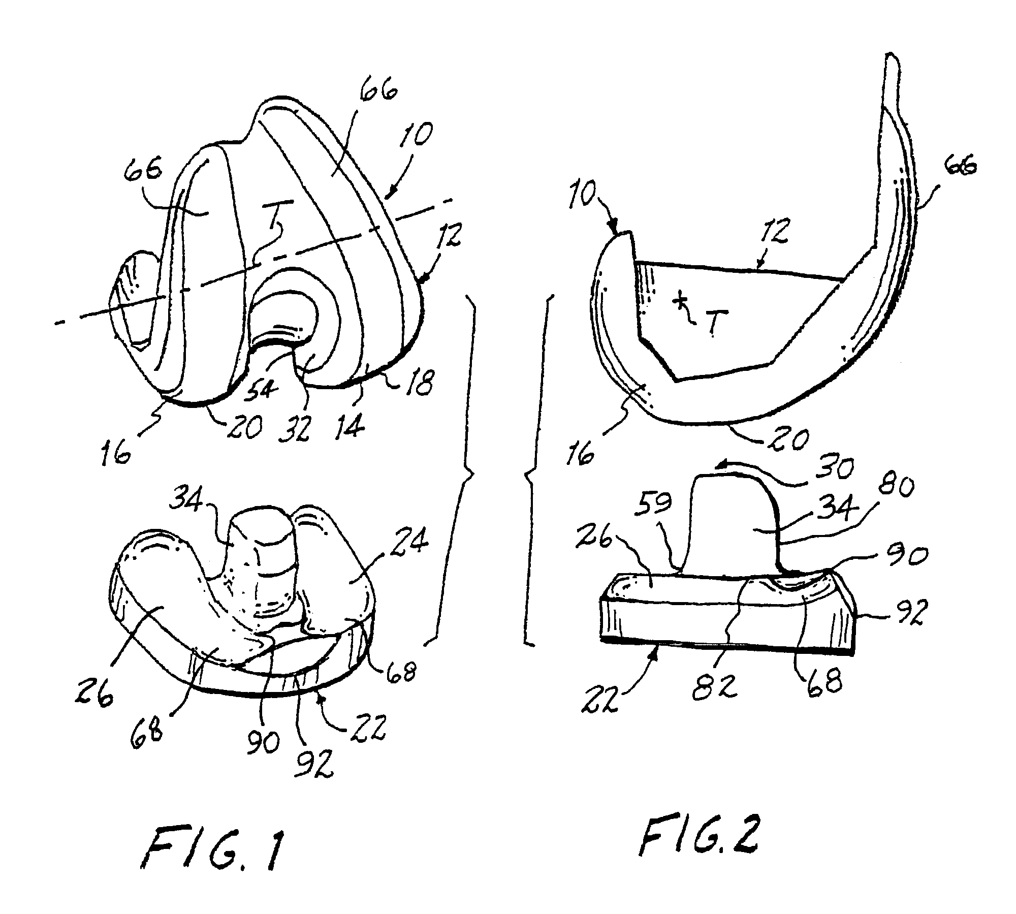
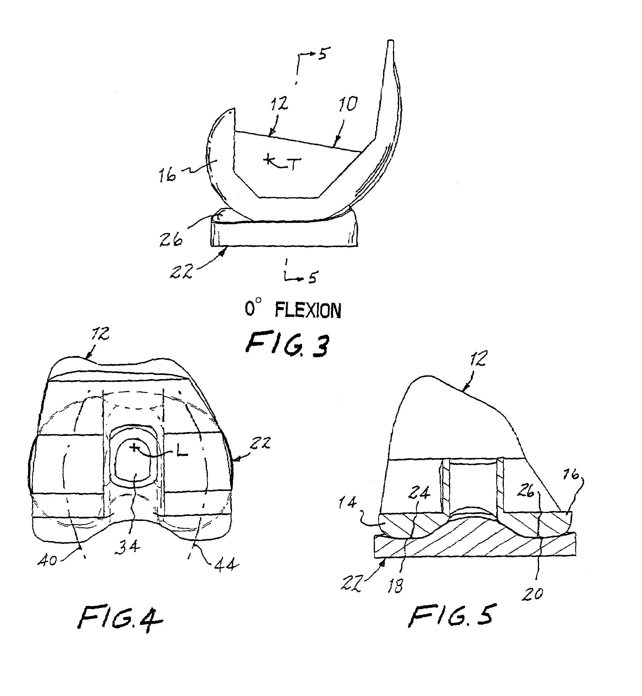
[0030]Referring now to the drawing, and especially to FIGS. 1 and 2 thereof, a knee prosthesis constructed in accordance with the present invention is shown at 10 and is seen to comprise a femoral component 12 having condylar elements illustrated in the form of condyles including a lateral condyle 14 and a medial condyle 16. Each condyle 14 and 16 includes a condylar surface 18 and 20, respectively. A tibial component 22 has articular surfaces including a lateral articular surface 24 for engagement with lateral condylar surface 18 of lateral condyle 14, and a medial articular surface 26 for engagement with medial condylar surface 20 of medial condyle 16, for rotation about a transverse axis of rotation T.

[0031]In the total knee replacement provided by knee prosthesis 10, both the anterior and the posterior cruciate ligaments are sacrificed, and knee prosthesis 10 includes a stabilizing mechanism 30 for stabilizing the engagement between the lateral condyle 14 and the lateral articul...


PUM


Abstract

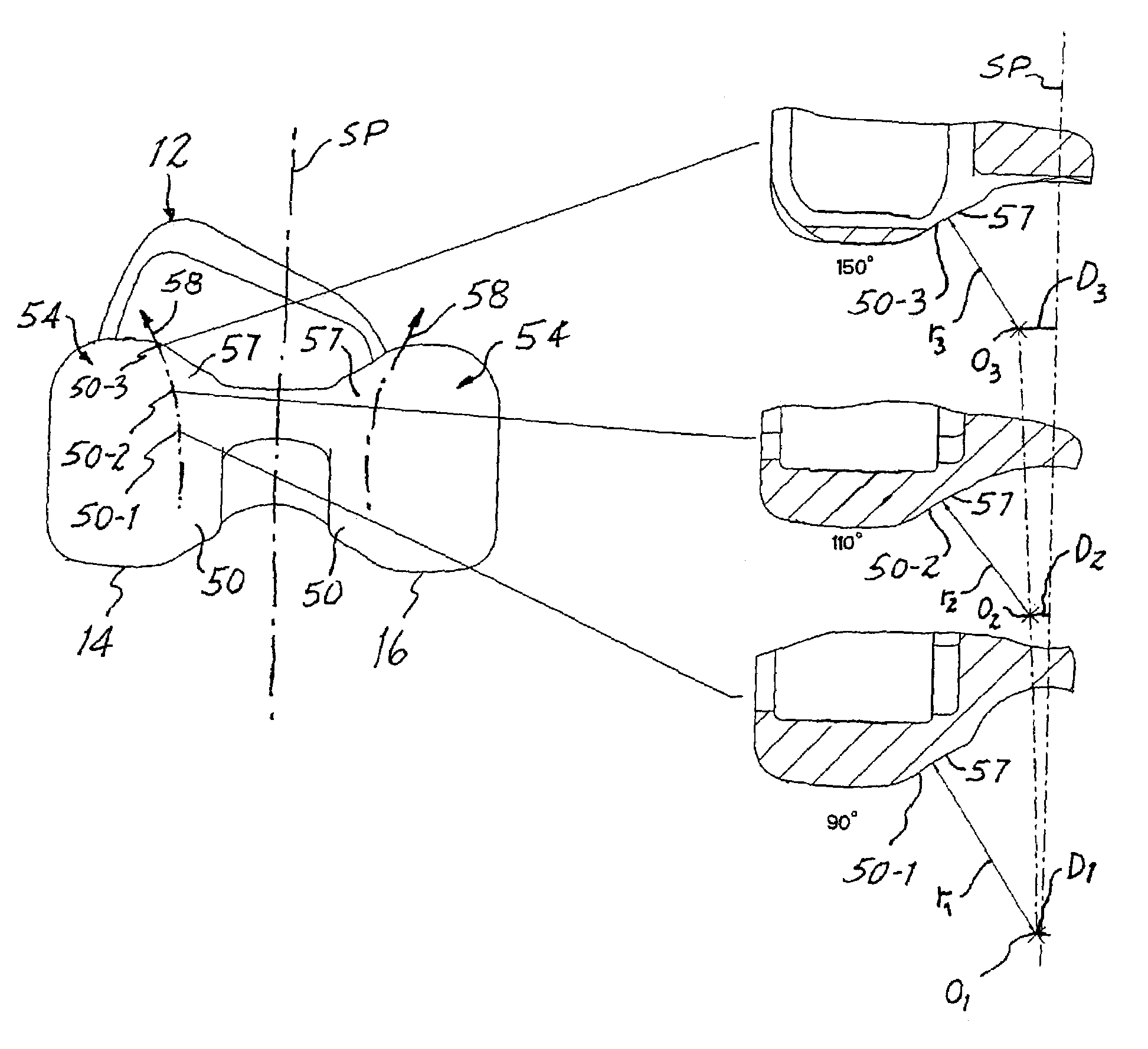
In a knee prosthesis, the condylar surfaces of a femoral component engage corresponding articular surfaces of a tibial component along prescribed tracks of predetermined curvature which enable relative rotation between the femoral component and the tibial component about a longitudinal axis during articulation of the knee prosthesis, and at least the condylar surfaces or the articular surfaces are flared in a direction away from corresponding articular surfaces or condylar surfaces along engaged posterior and anterior portions of the condylar surfaces and articular surfaces to provide an increased area of contact in deep flexion and in extended hyperextension for reducing contact stresses and concomitant wear while militating against unwanted distraction of the knee prosthesis. In addition, the radius of curvature of the condylar surfaces is reduced along posterior portions of the condylar surfaces to further avoid distraction of the knee prosthesis in deep flexion, thereby enabling deep flexion with greater ease and without excessive contact forces between the femoral component and the tibial component in deep flexion.

Description

BACKGROUND OF THE INVENTION[0001]1. Field of the Invention[0002]The present invention relates generally to the replacement of a natural kneejoint with a knee prosthesis and pertains, more specifically, to achieving an extended range of motion with reduced contact stresses within the components of the knee prosthesis and concomitant improved articular performance, together with greater longevity.[0003]During articulation of a natural kneejoint, flexion between the tibia and the femur takes place about a transverse axis while, at the same time, some relative rotation between the tibia and the femur occurs about a longitudinal axis. Such flexion and rotation is necessary to carry out a normal gate cycle. In addition, the femur experiences posterior rollback, that is, a combination of backward rolling and sliding of the distal femur along the proximal tibia as the knee flexes. Stability of the knee, during flexion and extension, depends, in part, upon the action of the cruciate ligament...

Claims


Application Information

Patent Timeline
Patent Type & Authority Patents(United States)
IPC IPC(8): A61F2/38
CPCA61F2/3886
Inventor SERVIDIO, DAMON J.
Owner HOWMEDICA OSTEONICS CORP
Learn More