

Magnetic core for transformer
A transformer and magnetic core technology, applied in the direction of transformers, fixed transformers, transformer/inductance parts, etc., can solve the problems of transformer device influence, magnetic flux difficult to flow, and reluctance increase, etc., to suppress vibration and reduce magnetization force, reducing the effect of magnetic resistance
- Summary
- Abstract
- Description
- Claims
- Application Information
AI Technical Summary
Problems solved by technology
Method used
Image

Examples
Embodiment 1
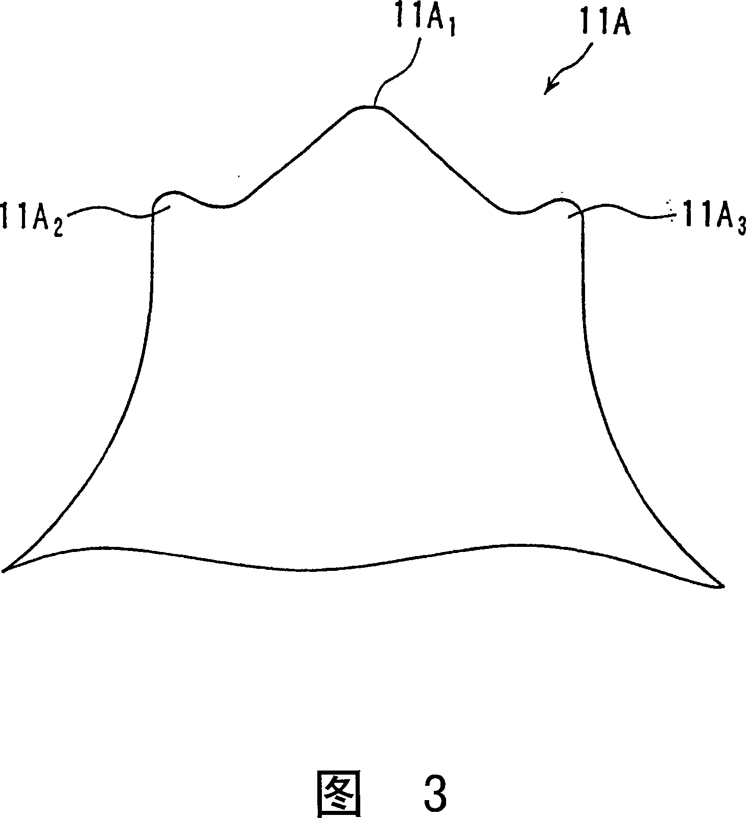
[0051] In this embodiment, FIG. 7 shows the size of the front end of the I-shaped core 1 of the magnetic core for a transformer according to the present embodiment, that is, each part shown in FIG. 3 . In addition, in this embodiment, the sizes of the tip of the first C-shaped core 2 ( FIG. 5 ) and the tip of the second C-shaped core 3 are shown in FIG. 8 . In this embodiment, the clamping portion 11A of the I-shaped core 1 is formed by a circular arc. 2 , 11A 3 The bend has a radius of value R0.3. In addition, the clamping portion 11A is formed with a circular arc 2 Clamped, clamping portion 21A of the first C-shaped core 2 2 The bend has a radius of value R0.25. The same applies to the second C-type core 3 .
[0052] That is, in this embodiment, the clamping portion 11A of the I-shaped core 1 2 , 11A 3 and the clamping portion 21A of the first C-shaped core 2 2 and the clamping portion of the second C-shaped core 3 are different in size. In short, even the case wher...
Embodiment 2
[0054] In this embodiment, a case will be described where the radii of the lobe portions and corner portions of the I-shaped core 1 are set to R3.0. FIG. 9 is a diagram showing the magnetic flux density distribution of the magnetic core for a transformer according to the present embodiment. In addition, in FIG. 9 and the following figures, although a part of the fitting between the I-shaped core 1 and the second C-shaped core 3 is taken as an example, other fitting parts are the same. In addition, in Figure 9 and the following figures, the closer the color of the area is to blue, the more sparse the magnetic flux is, and the closer the area is to red, the denser the magnetic flux is. As indicated by the arrow P1 in FIG. 9 , in order to maintain the characteristics (low reluctance, etc.) when the I-shaped core 1 and the second C-shaped core 3 are fitted and the mechanical fit between the cores, the tip is placed on the center line. At the intersection, a locking mechanism of 1...
Embodiment 3
[0059] In this embodiment, the case where the radius of the lobe portion and the corner portion of the I-shaped core 1 is R5.0 will be described. Fig. 12 is a diagram showing the magnetic flux density distribution of the magnetic core for a transformer according to the present embodiment. Although the shape of the front end of the I-shaped core 1 is the same as that of Example 2 as shown by arrow P31 in FIG. will disappear, adding ideal, green flux density regions throughout the magnetic circuit. In addition, as the radius becomes larger, as shown by arrow P41 in FIG. 13 , the leakage magnetic flux at the front end portion of the I-shaped core 1 decreases compared to Example 2.
[0060] On the other hand, as shown by the arrow P51 in FIG. 14, if the conventional technology (Patent Document 1) in which the front end of the I-shaped core is triangular is adopted, the magnetic flux density distribution has many yellow regions. Compared with the present embodiment, The flux dist...
PUM
 Abstract
Description
Claims
Application Information