Carrying system

A transfer system and transfer device technology, applied in the field of systems, can solve problems such as difficulty in correctly detecting deflection, sliding fork acceleration error, etc., and achieve the effects of shortening transfer time, reducing impact, and low impact

Inactive Publication Date: 2008-04-02
MURATA MASCH LTD
View PDF1 Cites 9 Cited by
  • Summary
  • Abstract
  • Description
  • Claims
  • Application Information

AI Technical Summary

Problems solved by technology

However, it is difficult to accurately detect deflection with sensors such as strain gau

Method used


Image

  • Carrying system
  • Carrying system
  • Carrying system

Examples


Embodiment Construction

[0017] Preferred examples for carrying out the present invention are shown below.

[0018] 【Example】

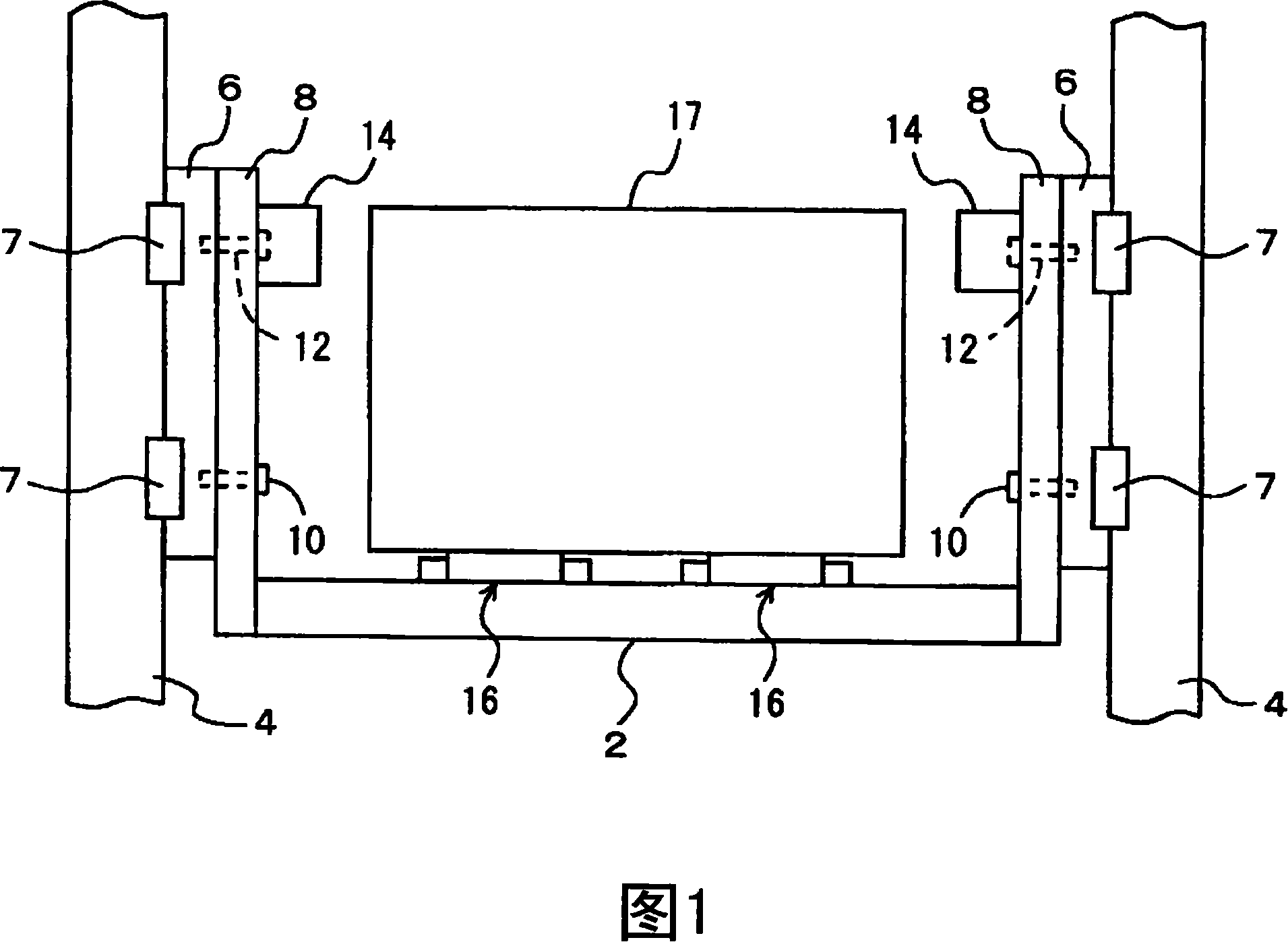
[0019] In FIGS. 1 to 8 , the transfer system of the embodiment is shown by taking a stacking crane as an example. In each figure, 2 is an elevating platform, which moves up and down, for example, along a pair of pillars 4, 4, and an unillustrated trolley of a stacking crane is provided at the lower part thereof, and travels on an unillustrated traveling rail. In addition, a traveling motor and an elevating motor of the elevating platform 2 are installed on the trolley. For example, the lift table 2 moves up and down along the pillar 4 through the left and right guide units 6, 6 and the linear motion guide (LM guide) 7. 8 is the upper frame of the lift table 2, and the pin 10 is used as the rocking center through the pins 10 and 12. It is mounted on the guide unit 6 in a freely tiltable manner.

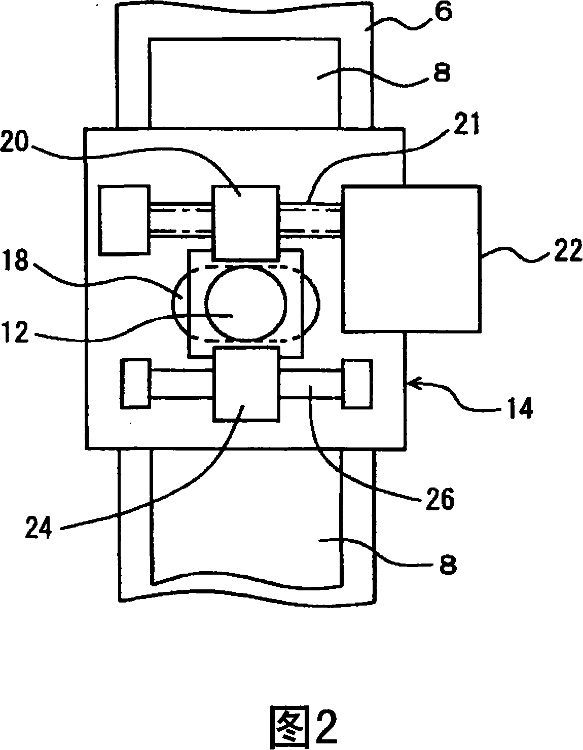
[0020] Fig. 2 shows tilting mechanism 14, and pin 12 is installed on the guide...


PUM


Abstract

A goods shelf (30) is provided with upper and lower signs (31, 32), and is detected by image sensors (36, 37) arranged on a sliding yoke (16). The incline of the sliding yoke (16) is also detected. A lift platform (2) is made incline to make the contact surface of the sliding yoke (16) and the articles. The invention can move articles in short time, with smaller space and low impaction.

Description

technical field [0001] The invention relates to a system that combines transfer devices such as stacking cranes or bridge cranes, rail trolleys, unmanned transport vehicles, and item platforms such as shelves. In particular, the invention relates to a system for correcting the inclination of a transfer device. Background technique [0002] It is known that when an article is transferred by the fork or the like, the fork is deflected due to its own weight and the load from the article. Therefore, Patent Document 1 proposes to correct the deflection of the sliding fork by inclining the lifting table on which the sliding fork is mounted. In order to perform the correction correctly, it is necessary to correctly detect the deflection of the slider. However, the extension and retreat of the slider and the acceleration caused by vibration constitute errors, and it is difficult to accurately detect deflection with sensors such as strain gauges. [0003] Patent Document 1: Japane...

Claims


Application Information

Patent Timeline
IPC IPC(8): B65G1/04
CPCB25J13/08B25J15/0014B65G1/0407B65G61/00B65G2203/042
Inventor 熊泽刚
Owner MURATA MASCH LTD
Why Eureka
Try Eureka