Dehumidifier

A dehumidifier and casing technology, which is applied to household heating, lighting and heating equipment, household heating and other directions, can solve the problems of foreign matter sticking, the filter 19 is easily damaged, etc., and achieves damage prevention, simple structure and cost saving. Effect

Inactive Publication Date: 2008-05-14
LG ELECTRONICS (TIANJIN) APPLIANCES CO LTD
View PDF0 Cites 4 Cited by
  • Summary
  • Abstract
  • Description
  • Claims
  • Application Information

AI Technical Summary

Problems solved by technology

[0006] However, in the dehumidifier of the prior art, since the filter 19 is exposed on the back of the dehumidifier, the filter 19 is easily damaged, and at the same time, foreign matter will stick to the filter 19 when the dehumidifier is not in use.

Method used


Image

  • Dehumidifier
  • Dehumidifier
  • Dehumidifier

Examples


Embodiment Construction

[0043] Below in conjunction with accompanying drawing and specific embodiment the present invention is described in further detail:

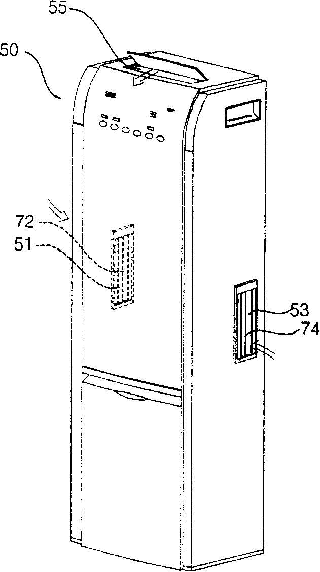
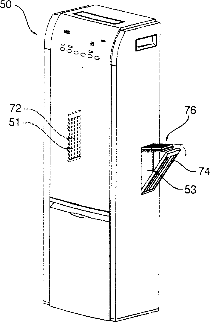
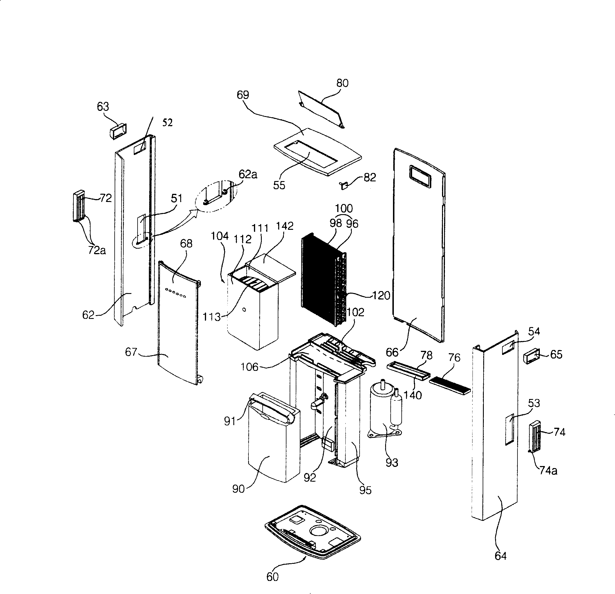
[0044] Such as figure 1 and figure 2 As shown, the dehumidifier of this embodiment has air inlets 51 and 53 for sucking in indoor air and an air outlet 55 for discharging dehumidified air into the room on the casing 50 constituting the appearance.

[0045] The air inlets 51 and 53 are formed on at least one of the upper surface, the front surface, the rear surface, the left side surface, and the right side surface of the casing 50 . In order to quickly inhale and dehumidify the indoor air, only the left air inlet 51 is formed on the left side of the casing 50 and the right air inlet 53 is formed on the right side of the casing 50. to explain.

[0046] The air outlet 55 is formed on at least one of the top, front, back, left side, and right side of the casing 50, and should be formed in the machine in order to discharge the dehumidified air ...


PUM


Abstract

The invention discloses a dehumidifier, which comprises a shell that is provided with an air absorbing inlet, an air discharging outlet and a water holding barrel containing space, a heat exchanger that consists of an evaporator and a condenser and is used for leading the air absorbed through the air absorbing inlet in sequence to operate heat exchanging, a water holding barrel that is contained in the water holding barrel containing space and used for storing the falling condensed water produced at the surface of the evaporator, a filter that enters into or goes out of the interior of the shell through the air absorbing inlet, and an absorbing grille that can protect the interior of the air absorbing inlet and can be rotatablely connected on the shell. The invention can prevent the breakage of the filter, and can keep the cleanliness of the filter, as well as bring convenience for the clearing or the replacing of the filter at the same time.

Description

technical field [0001] The invention relates to a dehumidifier, especially a dehumidifier in which a suction grill protecting the inside of the air suction inlet is provided on the air suction inlet for sucking indoor air, and a filter is installed while the suction grill is rotating. Background technique [0002] Such as Figure 7 and Figure 8 As shown, the dehumidifier in the prior art includes: a casing 1 that constitutes the appearance of the left and right sides and the top, and the front, rear and bottom surfaces are open; the evaporator 2 and the condenser 3 that are arranged inside the casing 1 The heat exchanger 4 for dehumidification; the compressor 10 for compressing the refrigerant circulating in the evaporator 2 and the condenser 3; it is arranged in front or behind the heat exchanger 4 and generates wind power to suck the indoor air into the casing 1 and then discharged to the indoor blower fan 5a and motor 5b; arranged in front of the casing 1, so that the d...

Claims


Application Information

Patent Timeline
Patent Type & Authority Applications(China)
IPC IPC(8): F24F1/02F24F13/28
Inventor 尹相渊
Owner LG ELECTRONICS (TIANJIN) APPLIANCES CO LTD
Why Eureka
Try Eureka