Hose clamping device

A hose and clamping mechanism technology, applied in the field of hose clamps, can solve the problems of poor sealing safety performance, insufficient clamping force of high-pressure pipes, inconvenient loading and unloading, etc., achieving considerable economic benefits, saving manpower, material resources and financial resources, good performance

Active Publication Date: 2010-12-22
DALIAN CONSERVATION SCI & TECH CO LTD
View PDF3 Cites 0 Cited by
  • Summary
  • Abstract
  • Description
  • Claims
  • Application Information

AI Technical Summary

Problems solved by technology

And the existing hose clamping device, the structure is simple and crude, such as the connection at the household gas pipeline interface is tightened with a metal wire, and the compressed gas output hoses such as the nozzles used for cleaning on the factory site or the anti-aircraft spray guns are clamped with U-shaped clamp screws. , to varying degrees, there are problems such as inconvenient loading and unloading, poor sealing safety performance, sharp corners and corners that are easy to scratch personnel or damage hoses; the structure is complex
As disclosed in PCT patent application 02825291.8 (publication number CN1605005A), see figure 1 , figure 2 , and as described in application number 01802897.7 (publication number CN1420975A, authorized announcement number CN1187550C), see image 3 , Figure 4 On the one hand, its structure is complicated, usually it must be made of all metal, and the processing cost is high. On the other hand, special tools are required for its installation or disassembly, which is troublesome and unsightly. If the hose is hard, it is difficult to install; at the same time, The above two structures also have the problem of insufficient clamping force for high-pressure pipes with high internal pressure.
Scratch-prone when used on fuel guns such as gas stations or construction sites

Method used


Image

  • Hose clamping device
  • Hose clamping device
  • Hose clamping device

Examples


Embodiment 1

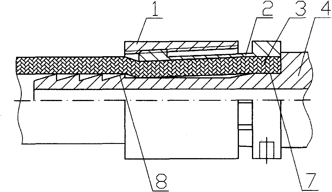
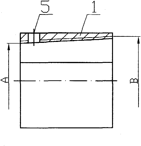
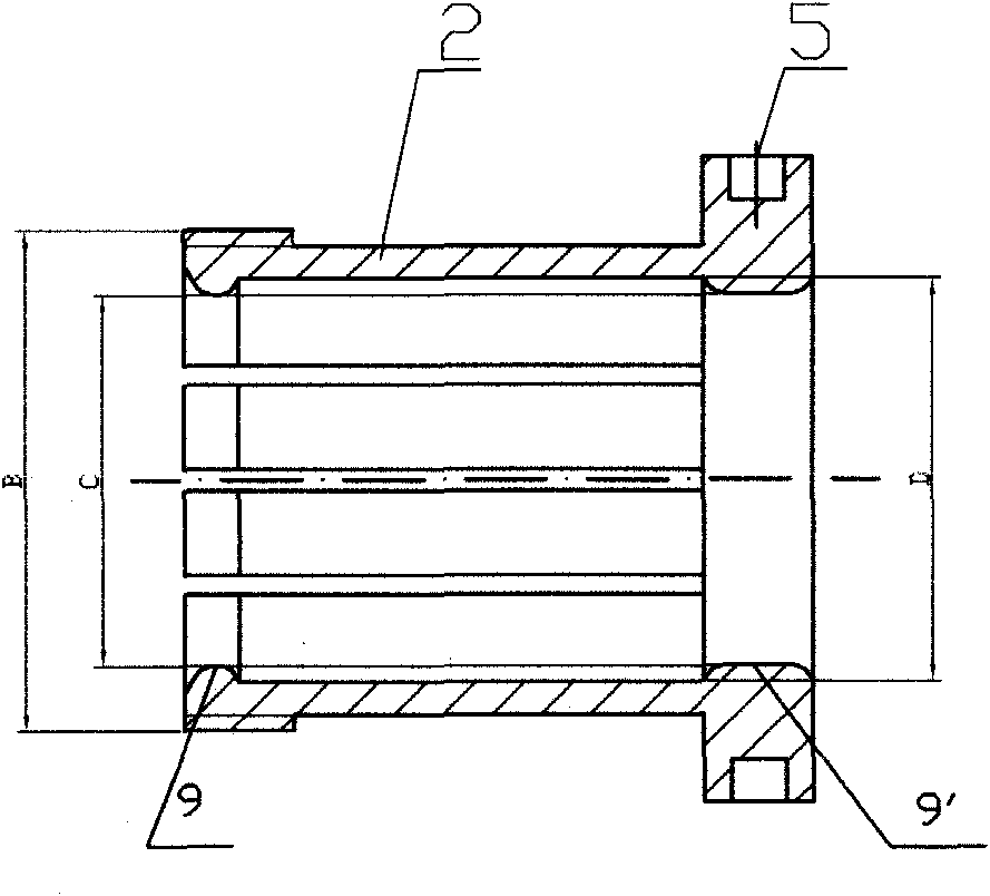
[0045] A hose clamping mechanism such as Figure 9 As shown, it includes a hose joint 4 coaxial with the hose 3, an inner cone nut 1 and a pipe bolt 2, the outer diameter of the hose joint 4 matches the inner diameter of the hose 3, and the inner cone nut 1, such as Figure 6 As shown, the large aperture end is the screw-in end, and the corresponding small aperture end is the end of the inner cone nut 1; the internal thread of the inner cone nut 1 is a tapered thread, and the small diameter of the thread at the end of the inner cone nut 1 A is slightly larger than the outer diameter of the hose; the pipe bolt 2, such as Figure 7 , Figure 8 As shown, the threaded end is evenly distributed along the circumferential direction of the pipe wall with more than two long strips parallel to the central axis, and the inner diameter C of the central hole is slightly larger than the outer diameter of the hose. When using this hose clamping device to clamp the hose, first insert the h...

Embodiment 2

[0054] Such as Figure 10 As shown, it is also an embodiment of the present invention. The difference from Embodiment 1 is that there are flanges 9 and 9' on the inner sides of the two ends of the pipe bolt 2 respectively, and the inner diameters of the flanges 9 and 9' are slightly It is larger than the outer diameter of the hose; the joint where the flange 9 away from the head of the pipe bolt 2 and the hose is arc-shaped, that is, the clamping position. This design is also to increase the clamping force, make the connection reliable, or be used in occasions with high working pressure.

[0055] The hose joint 4 of the present invention can be a joint of symmetrical shape that connects two or more directions, so as to realize the connection between two or more hoses. Such as Figure 11 As shown, the left and right symmetrical double hose joints 6 are used, and the rest of the structure is the same as that of the embodiment 2, which is used for clamping and connecting two ho...


PUM


Abstract

The invention relates to a hose clamping device, comprising a hose joint. The clamping device is characterized in that: the clamping device also comprises an inner cone nut and a pipe bolt matched with each other; a big-aperture end of the inner cone nut is a screw-in end, and a small-aperture end corresponding to the big-aperture end is the tail end of the inner cone nut; an inner thread of the inner cone nut is a tapered thread; the thread small diameter A of the tail end of the inner cone nut is slightly more than the outer diameter of a hose; more than two strip openings parallel to a central shaft are uniformly distributed at a threaded end of the pipe bolt in the circumferential direction of a pipe wall; the inner diameter C of a central hole of the pipe bolt is slightly more than the outer diameter of the hose. The clamping device is safe, practical, simple in structure, good in service performance, excellent in economic benefit and extensive in application, can be made of metal material or nonmetal material, can be widely used in all aspects of production, life, industry and agriculture, and can produce good economic benefit and social benefit.

Description

technical field [0001] The invention relates to a hose clamp, in particular to a hose clamping device. Background technique [0002] As we all know, regardless of vehicles, equipment or daily life, whether it is used to transport liquid or gas, whether it is used under normal pressure or under high pressure, the use of hose clamping devices abounds, with a large amount of use and a wide range of applications The vastness is self-evident. And the existing hose clamping device, the structure is simple and crude, such as the connection at the household gas pipeline interface is tightened with a metal wire, and the compressed gas output hoses such as the nozzles used for cleaning on the factory site or the anti-aircraft spray guns are clamped with U-shaped clamp screws. , to varying degrees, there are problems such as inconvenient loading and unloading, poor sealing safety performance, sharp corners and corners that are easy to scratch personnel or damage hoses; the structure i...

Claims


Application Information

Patent Timeline
Patent Type & Authority Patents(China)
IPC IPC(8): F16L33/24
CPCF16L33/025F16L33/224F16L33/226F16L33/035
Inventor 王嘉贤王媛媛
Owner DALIAN CONSERVATION SCI & TECH CO LTD
Why Eureka
Try Eureka