Transmission mechanism of combing machine detaching roller

A technology for separating rollers and transmission mechanisms, which is applied to combers, transmission devices, gear transmission devices, etc., can solve the problems of low motion accuracy, increased cost, and large number of components, and achieve the effect of improving transmission control accuracy and simple structure.

Inactive Publication Date: 2008-11-26
胡平 +1
View PDF4 Cites 14 Cited by
  • Summary
  • Abstract
  • Description
  • Claims
  • Application Information

AI Technical Summary

Problems solved by technology

Therefore, the number of components is large, the design calcul...

Method used


Image

  • Transmission mechanism of combing machine detaching roller
  • Transmission mechanism of combing machine detaching roller
  • Transmission mechanism of combing machine detaching roller

Examples


Embodiment Construction

[0015] specific implementation plan

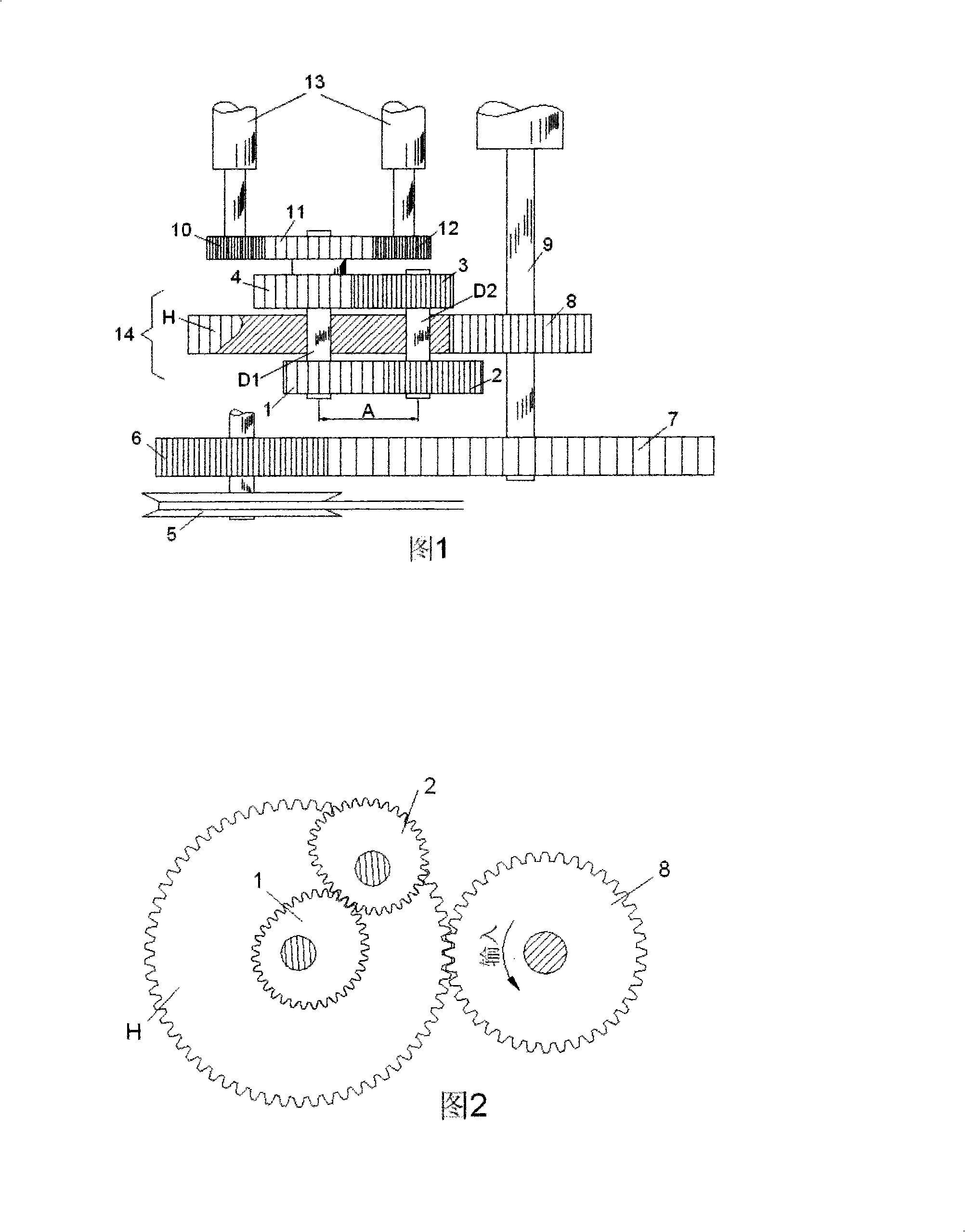
[0016] As shown in Figure 1, the cylinder shaft (9) is driven by the belt pulley (5) through the gear (6) and the gear (7). The gear (8) fixed on the cylinder shaft (9) drives the tie rod (H) to rotate at a constant speed around the shaft (D1). The planetary gear (2) and the planetary gear (3) rotate around the axis of the shaft (D2) while revolving at a constant speed with the tie rod (H) around the shaft (D1).

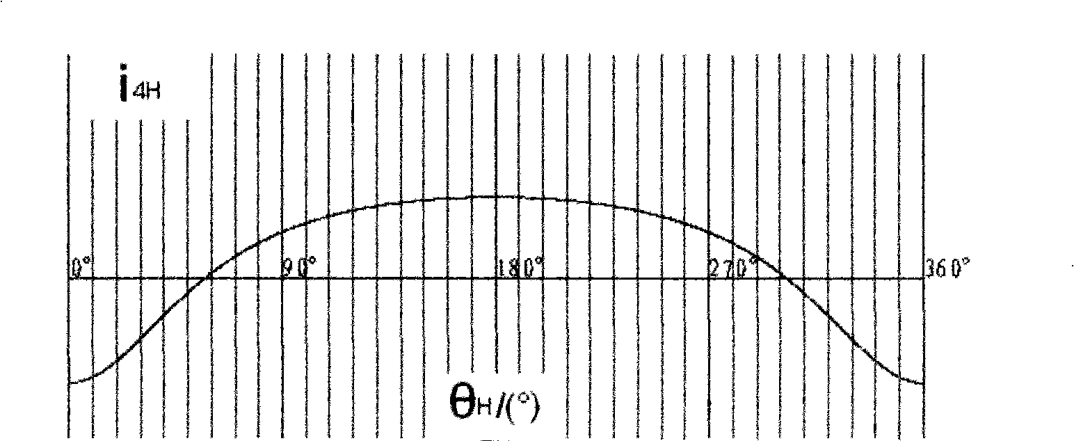
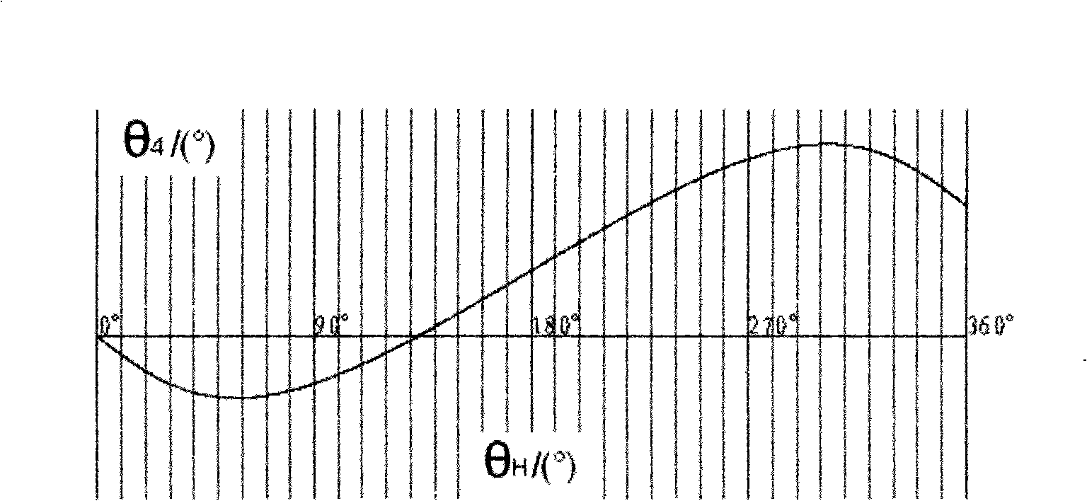
[0017] The sun gear (1) is fixed on the frame (not shown) and does not rotate, and the planetary gears (2), planetary gears (3) are rigidly connected with the shaft (D2). The rotational angular speeds of the planetary gear (2) and the planetary gear (3) are the same and constantly changing, thereby driving the sun gear (4) to rotate in variable speed and direction. And then drive the gears (10), (12) by the gear (11) that is connected with the sun gear (4) to transmit the shifting and direction changing rotation to the detachin...


PUM


Abstract

The invention relates to a transmission mechanism of a detaching roller on a combing machine which is provided with a non-circular planetary gear train. The mechanism comprises two sun gears, a tie bar and an even number of planetary gears. The transmission mechanism outputs variable motions including natural rotation, stop and reversion in every working circle (which means the 360 degree rotation of a cylinder), drives the detaching roller to change the speed and the direction of the rotation in accordance with the requirements of the process when the tie bar is rotating at the constant speed driven by a single power source by constructing a pitch curve of the non-circular gear.

Description

technical field [0001] The invention relates to a transmission mechanism of a separating roller of a combing machine, in particular to a non-circular planetary gear train transmission mechanism of the separating roller of a combing machine. Background technique [0002] In order to make the separating roller of the combing machine move according to the process requirements and achieve the expected effective output length (the difference between the total forward rotation amount and the total reverse amount), the transmission of the existing combing machine separation roller adopts the following two modes to realize; 1) It is realized by the combination of the planar linkage mechanism and the differential epicyclic gear train; 2) It is realized by the combination of a conjugate cam, a group of four linkages and the differential epicyclic gear train. Due to the motion synthesis of the differential mechanism, the speed change and direction change motions such as forward rotatio...

Claims


Application Information

Patent Timeline
IPC IPC(8): D01G19/26F16H3/44
Inventor 胡平杨决宽
Owner 胡平
Why Eureka
Try Eureka