Spring spindle

A spindle and compression spring technology, applied in the field of spring spindles, can solve the problems of insufficient pay-off speed, large pay-off resistance of the line tube, easy breakage of movable pins, etc., to improve the weaving quality and production efficiency, reduce the number of broken lines, The effect of low pay-off resistance

Inactive Publication Date: 2010-06-09
张宝香
View PDF8 Cites 0 Cited by
  • Summary
  • Abstract
  • Description
  • Claims
  • Application Information

AI Technical Summary

Problems solved by technology

[0005] After years of continuous improvement, the above-mentioned patents have played a certain role and effect in improving product quality. However, after regular operation and use, it is found that the existing spring spindles still have some defects, such as the large resistance of the line pipe to the line. The speed is not fast enough, which affects the weaving speed and quality of the knitting machine. At the same time, the movable pin of the positioning device needs to be opened and closed frequently due to the exchange of the wire tube, but its strength is poor. The movable pin is easy to break, the service life is short, and frequent maintenance is required. users add a lot of trouble

Method used


Image

  • Spring spindle
  • Spring spindle
  • Spring spindle

Examples


Embodiment Construction

[0014] Embodiments of the present invention will be further described below in conjunction with the accompanying drawings.

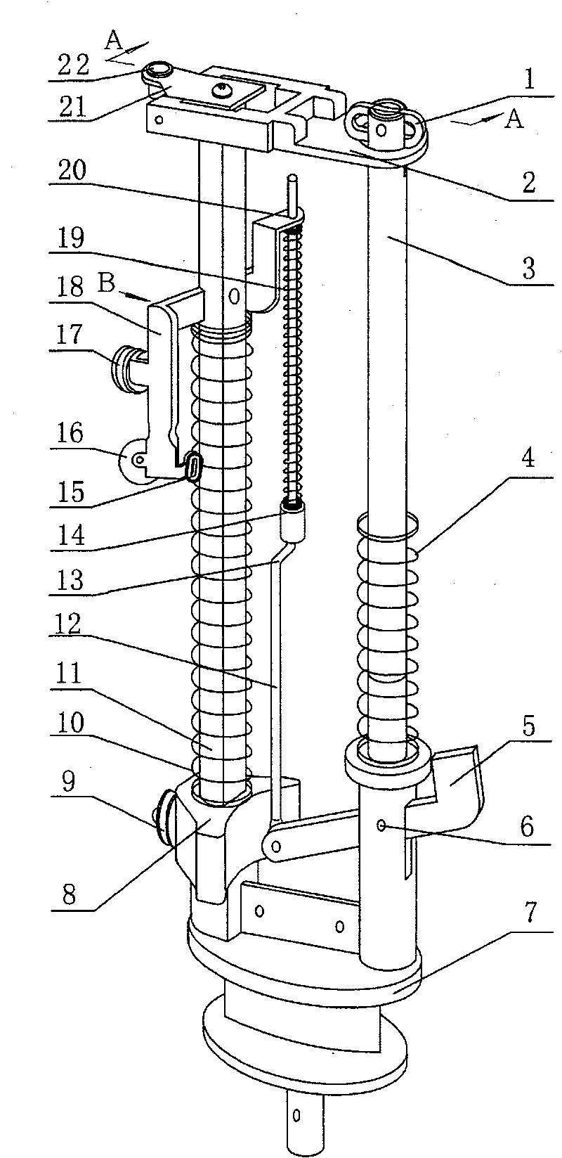
[0015] Left and right columns 3,11 are die-cast in two through holes at the top of the runway bar 7, and are fixed into one body to form a fixture.

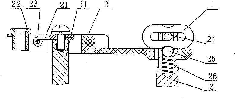
[0016] The left column 3 is cylindrical, and there is an open slot in the middle of the top, and small springs 26 and steel balls 25 are placed in the slot. Through two through holes, the lock buckle 1 with the waist hole in the middle is connected to the opening groove of the left column, and the lock buckle 1 can rotate around the second pin 24, and cooperates with the small spring 26 and the steel ball 25.

[0017] Right column 11 sections are waist-shaped, and screw hole is arranged on the top.

[0018] The track bar 7 is the same as the prior art by injection molding of composite material, wear-resistant and low noise.

[0019] In the middle of the connecting rod 12, there is a vertical transverse tu...


PUM


Abstract

The invention relates to a spring spindle, wherein, a fixed piece is formed by fixing a right upright post which is fixed with a support and a connecting rod and a left upright post on a track rod, and the spring spindle is formed by connecting a weaving piece and the fixed piece into a whole through a pressure plate and a switch plate; the support is flanged; a pulley is divided into an upper pulley and an intermediate pulley; the upper pulley and the intermediate pulley which are connected to the support are arranged on the right of the right upright post; mounting axial lines of the upper pulley and the intermediate pulley are crossed and angulated at 57 to 63 DEG; a vertical and bended straight section on the middle of the connecting rod is provided with a limit rod; and the pressure plate is matched with a lock catch which is connected to the left upright post. The support is arranged on the right of the right upright post instead of being arranged on the left of the right uprightpost, thereby the angle between a leading-in porcelain eye and a thread-passing point is reduced to between 27 and 33 DEG; the angle is smaller, the pay-out resistance on bobbin is smaller, and thenthe pay-out speed is quick and the thread breakage time is greatly reduced; the connecting rod and the support are arranged on both sides of the right upright post so as to maintain routing balance, thereby the speed can be improved by 10 percent and the weaving quality and the production efficiency are greatly improved; and simultaneously the pressure plate has good strength and long service life, is convenient, quick and easy to operate, and is an updated product of the third generation.

Description

technical field [0001] The invention relates to a main braiding part on a braiding machine, especially for braiding wires, cables, glass fiber tubes, ropes, automobile and motorcycle assembly lines, liquefied gas hoses, rubber reinforced tubes, braided tubes, etc. The spring spindle used on the machine. Background technique [0002] Patent No. CN92222751.9 "Low-noise spring spindle" provides a kind of spindle used on the braiding machine, and by installing an adjustment device on the column, it solves the phenomenon of inner looseness and outer tightness of the braiding thread during the weaving process, and The weaving quality is good, and at the same time, the running noise is reduced by 80% compared with the commonly used spindles. [0003] Patent No. CN01246185.7 "Spring Spindle" improves the structure of the movable pin. One end of the movable pin is connected with the left column, and the opening hook at the other end is hooked into the through hole at the end of the ...

Claims


Application Information

Patent Timeline
Patent Type & Authority Patents(China)
IPC IPC(8): D01H7/04D04C3/40
Inventor 张宝香
Owner 张宝香
Why Eureka
Try Eureka