Washing machine

A washing machine and washing tub technology are applied in the field of washing machines to achieve the effects of improving washing performance, saving detergent and improving circulation capacity

Inactive Publication Date: 2012-10-24
PANASONIC CORP
View PDF2 Cites 0 Cited by
  • Summary
  • Abstract
  • Description
  • Claims
  • Application Information

AI Technical Summary

Problems solved by technology

In this way, if the existing washing machine structure is adopted, it is impossible to only improve the ability of raising the hydrofoil.

Method used


Image

  • Washing machine
  • Washing machine
  • Washing machine

Examples


Embodiment 1

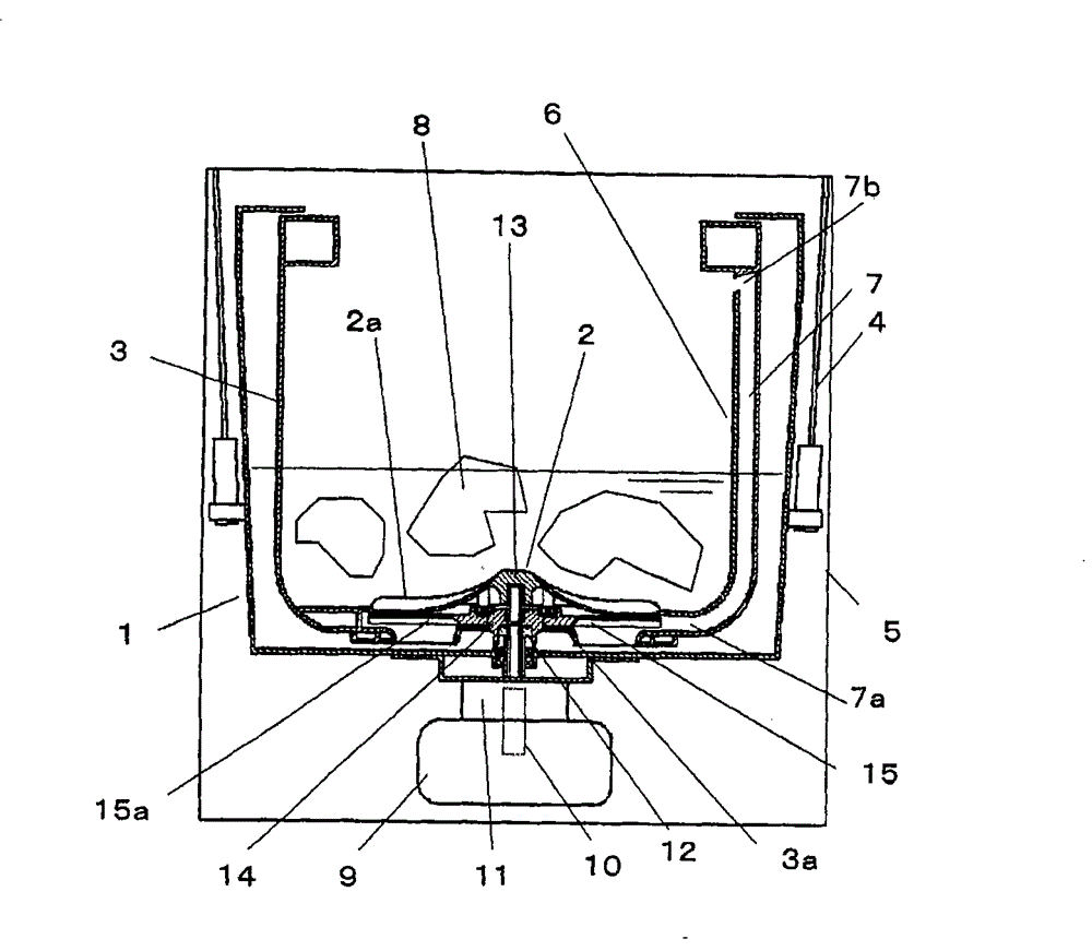
[0037] The inside of the bucket 1 of the washing machine is provided with a washing and dehydrating bucket (hereinafter referred to as the washing tub) 3, the bottom of the washing tub 3 is provided with a rotating wing 2 that can rotate freely, and the washing tub 3 is suspended on the shell 5 of the washing machine through the hanging rod 4 . The inner wall of the washing tub 3 is equipped with a pumping channel shell 6, and more than one independent pumping channel 7 is formed between the pumping channel shell 6 and the washing tub 3. On the upper surface of the rotary blade 2, a convex stirring blade portion 2a for stirring the laundry 8 is provided.

[0038] The bottom surface of the water tub 1 is fixed with a drive motor 9, and the motor drive shaft 10 is divided into two coaxial shafts after passing through the reduction gear 11. The outer bucket rotation drive shaft 12 is fixed to the bottom 3a of the washing tub 3, so that the washing tub 3 rotates; the inner drive ...

Embodiment 2

[0054] Such as Figure 8 As shown, a part or all of the rotating wing 2 is made of a transparent or translucent material 24, so that the rotating state of the hydrofoil 15 can be confirmed visually. Other constitutions are the same as those of Embodiment 1. In this way, the bad state of the transmission part such as the speed increasing mechanism can be found quickly.

Embodiment 3

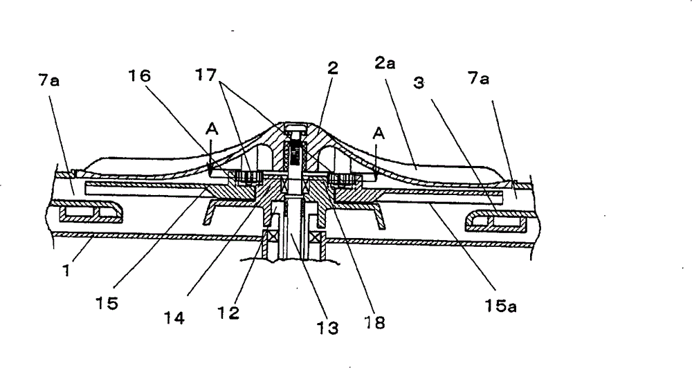
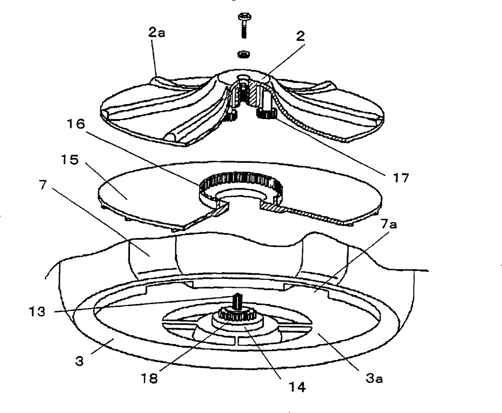
[0056] Figure 9 It is an enlarged view showing a longitudinal section of the rotating wing portion of the washing machine in Embodiment 3 of the present invention, Figure 10 It is a three-dimensional exploded view of the rotating wing part of the washing machine after being partially cut off. For the same parts as in Embodiment 1, repeated descriptions thereof are omitted here.

[0057] A plurality of planetary gears 17 are rotatably supported on the rotary shaft by the bushing 2c of the rotor blade 2, the annular fixing device 24, and the fixing screw 25. As shown in FIG. In this way, not only the self-rotation of the planetary gear 17 can be realized through a simple structure, but also the mounting accuracy and strength of the planetary gear 17 can be improved. In this way, not only the durability of the speed increasing gear part can be improved, but also the meshing noise and vibration between the gears can be reduced.


PUM


Abstract

The aim of the invention is to improve circulation capability of wash water and improve clean degree of washing clothes. The invention relates to a washing machine comprising a rotating wing (2) arranged on inner bottom of a cylindrical washer (3), which can freely rotate; a water raising wing (15) arranged between the rotating wing (2) and the inner bottom of the cylindrical washer (3); and a speed increasing apparatus (11) for improving rotation speed of the water raising swing (15). The water raising swing (15) can get higher rotation speed by depending on the speed increasing apparatus (11) than depending on the rotating wing (2).

Description

technical field [0001] The present invention relates to a washing machine, and more particularly, to a washing machine for washing clothes by pumping and circulating washing liquid from a lower portion of a washing tub to an upper portion. Background technique [0002] In recent years, people have higher and higher requirements for washing machines to save water and detergent. However, when the amount of washing liquid and detergent is small, the amount of washing liquid soaked into the laundry will also decrease, resulting in a decrease in cleaning performance. Therefore, some washing machines are provided with a pumping channel on a part of the inner wall of the washing tub, and blades are provided on the underside of the rotating wing (wave wheel) at the bottom of the washing tub. The channel is led to the upper part of the washing drum, and then poured on the washing through the drain. In this way, a large amount of washing liquid is poured onto the laundry with great ...

Claims


Application Information

Patent Timeline
Patent Type & Authority Patents(China)
IPC IPC(8): D06F17/06D06F17/08D06F17/10D06F23/04D06F37/12D06F37/30D06F37/40D06F39/08
Inventor 广田弘美胁田克也渕上英巳越贺健二
Owner PANASONIC CORP
Why Eureka
Try Eureka