Combustor of inner flame gas range

A technology for burners and gas stoves, which is applied in the direction of gas fuel burners, burners, and combustion methods. Large flow, meet market demand, strong firepower effect

Inactive Publication Date: 2010-09-01
吴成年 +1
View PDF8 Cites 5 Cited by
  • Summary
  • Abstract
  • Description
  • Claims
  • Application Information

AI Technical Summary

Problems solved by technology

However, the various internal flame gas stoves seen in the market are limited by the structure of the burner and the combustion method. It is necessary to continue to increase the heat flow rate, and at the same time ensure that the combustion is stable and the CO and NOx in the combustion flue gas do not exceed the standard. with greater difficulty
Not to mention ensuring that the CO and NOx in the combustion flue gas do not exceed the standard, it is difficult for many burners to increase the total area of ​​the burner's fire hole only from the perspective of ensuring combustion stability; To ensure stable combustion, the best way to increase the total area of ​​fire holes is to increase the number of fire holes, which is also difficult for burners with trapezoidal, rectangular, and strip-shaped fire holes.
[0004] In order to increase the heat flow, some manufacturers set a conical section with double rows of circular fire holes on the inner flame burner. Although this can increase the heat flow of the burner, due to the structural limitations of the double row of fire holes , it is difficult to supplement the air between the upper and lower fire holes, and the improvement of heat flow is still difficult to meet the market demand
In addition, the internal flame burner with a circular fire hole is directly exposed above the burner, and it is difficult to avoid the occurrence of liquid and other dirt blocking the fire hole.

Method used


Image

  • Combustor of inner flame gas range
  • Combustor of inner flame gas range
  • Combustor of inner flame gas range

Examples


Embodiment approach

[0038]The implementation manners of several typical structural embodiments in the present invention are as follows:

[0039] (1) The structure of the single-cavity fire distributor device without air passage

[0040] Implementation of the first exemplary embodiment:

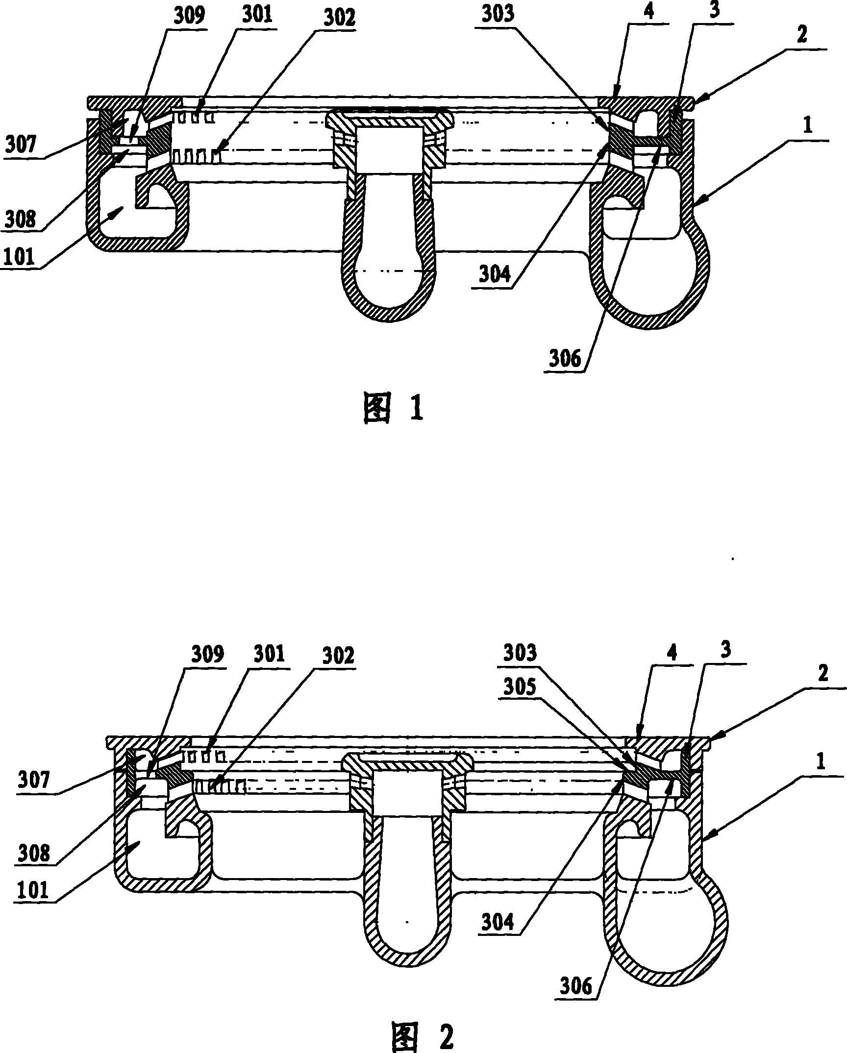
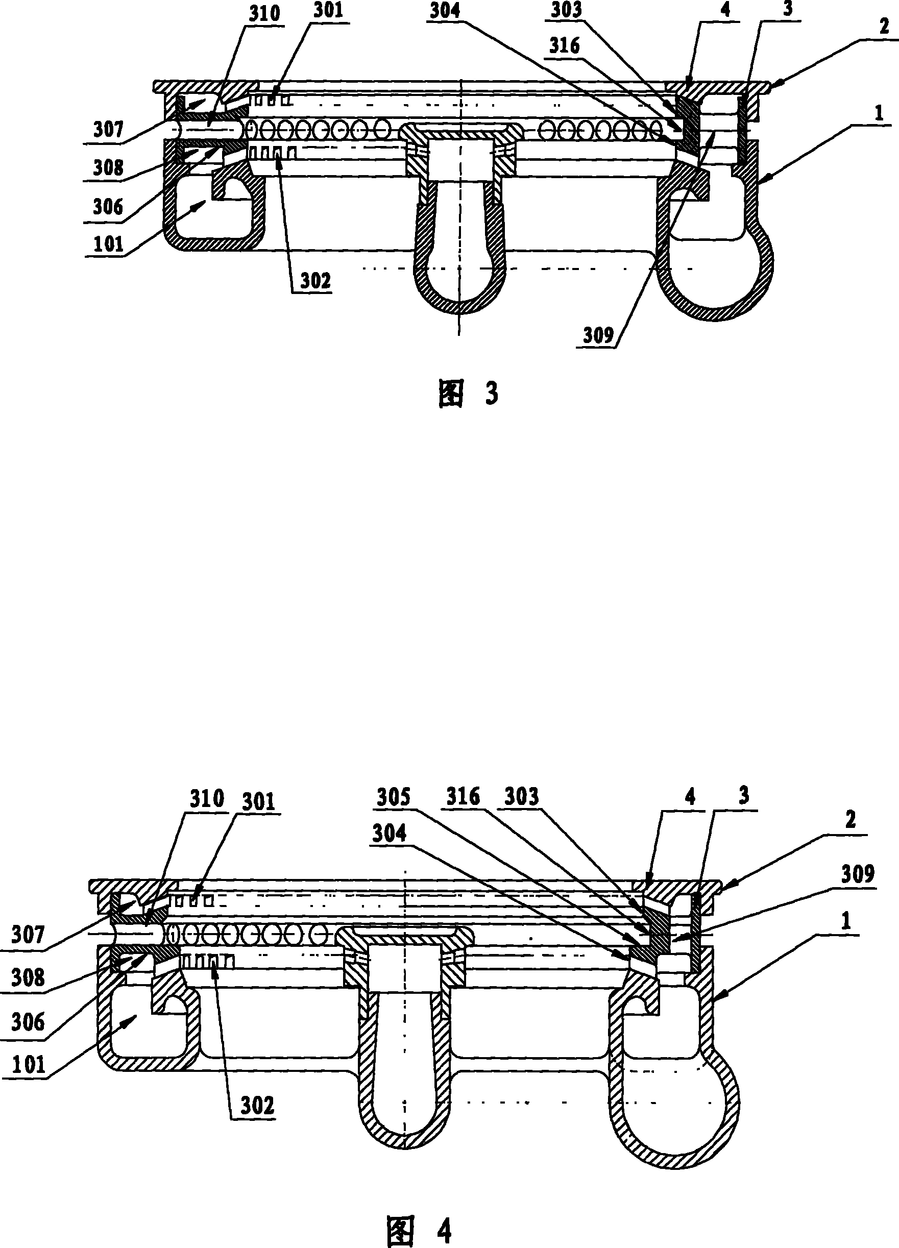
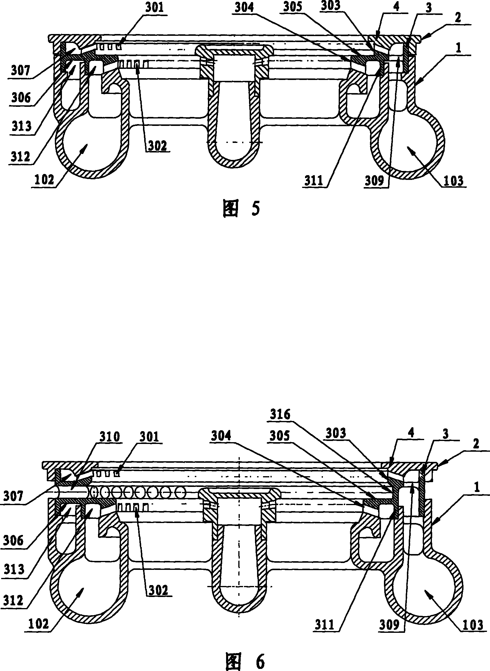
[0041] On the fire distributor device, upper and lower layers of fire holes 301, 302 are arranged along the inner circumference of the fire distributor main body, and the fire hole outlet direction is inward; The fire hole is arranged at the bottom of the cylindrical section 304 of the inner ring of the main body of the fire distributor; the section of the fire hole is trapezoidal, rectangular or strip-shaped; the cylindrical section where the upper fire hole is located is directly connected to the cylindrical section where the lower fire hole is located; in the main body of the fire distributor, A separation layer 306 is provided between the upper and lower fire holes, and the inner cavity of the main body of t...


PUM


Abstract

The invention discloses a burner of an inner flame gas stove, which consists of a burner body and a fire distributer device; an upper layer fire hole and a lower layer fire hole are arranged on the fire distributer device and the direction of the outlets of the fire holes is inward, and an air channel is arranged or not arranged between the upper layer fire hole and the lower layer fire hole; a single inner cavity or two independent inner cavities is or are arranged; the two independent inner cavities are arranged so that the flame at the upper layer and the lower layer can be regulated independently; while the air channel is arranged so that the air supplementation can be more abundant. The burner utilizes multiple-layer fire holes, stratified combustion and multiple-layer cyclonic flame, and has the advantages of large heat flow, fierce fire power, high heat efficiency, low-CO and low-NOx in smoke gas, no fire hole blocking and the like.

Description

technical field [0001] The invention relates to a burner for a gas stove, in particular to a burner for an inner flame gas stove. Background technique [0002] In recent years, internal flame gas stoves have been paid more and more attention to because of their high thermal efficiency and gas saving. However, there are few internal flame gas stoves with a heat flow greater than 4kW on the market at present, which is difficult to meet people's demand for large firepower internal flame gas stoves. [0003] To further increase the heat flow of the inner flame gas stove, the precondition is to ensure that the combustion condition is good and the harmful gas in the combustion flue gas cannot exceed the standard. However, the various internal flame gas stoves seen in the market are limited by the structure of the burner and the combustion method. It is necessary to continue to increase the heat flow rate, and at the same time ensure that the combustion is stable and the CO and NO...

Claims


Application Information

Patent Timeline
Patent Type & Authority Patents(China)
IPC IPC(8): F23D14/00F23D14/84F23D14/56F23D14/58
Inventor 吴成年
Owner 吴成年
Why Eureka
Try Eureka