Light guide plate, light guide plate assembly, and surface illuminating device and liquid crystal display device using these

A technology for lighting devices and light guide plates, which is applied to display devices, lighting devices, illuminated signs, etc., can solve the problem that the brightness of the exit surface and the brightness of the light-emitting surface cannot be fully achieved, and it is difficult to obtain high-brightness lighting. Problems such as thin light guide plate

Active Publication Date: 2009-07-01
FUJIFILM CORP
View PDF4 Cites 38 Cited by
  • Summary
  • Abstract
  • Description
  • Claims
  • Application Information

AI Technical Summary

Problems solved by technology

[0017] First, since the light from the light source enters from the side end surface of the light guide plate, there is a limit to the amount of incident light, and it is difficult to obtain high-brightness illumination light
[0018] Second, since the outer diameter of the currently available fluorescent tubes is at least about 2.0 mm, it is difficult to make the thickness of the light guide plate thinner than the outer diameter of the fluorescent tube, and as a result, it is difficult to further reduce the thickness of the light guide plate
However, as in the aforementioned Patent Documents 2, 3, and 4, in general, in the technology of planar lighting devices such as a light guide plate using LEDs as a light source, and a light guide plate type BLU, in addition to the problems of the light guide plate type BLU using fluorescent lamps, In addition, there are problems that it is difficult to reduce thickness and increase size due to the following reasons or problems
[0021] First, there is a limit to the light guide length of a side-light light guide plate such as a flat plate or a wedge shape, and the in-plane uniformity of the brightness of the exit surface and the brightness of the light-emitting surface cannot be fully achieved
[0022] Second, in the light guide plate of the prior art side-lighting method, when the light from the light source is incident from one side end face or both end faces, due to the arrangement pitch of the LEDs, the luminous density (1m / m 2 ) has a limit, so there is also a limit to the amount of incident light

Method used


Image

  • Light guide plate, light guide plate assembly, and surface illuminating device and liquid crystal display device using these
  • Light guide plate, light guide plate assembly, and surface illuminating device and liquid crystal display device using these
  • Light guide plate, light guide plate assembly, and surface illuminating device and liquid crystal display device using these

Examples


Embodiment Construction

[0094] The light guide plate, the light guide plate assembly, the planar lighting device and the liquid crystal display device using them of the present invention will be described in detail below based on preferred embodiments shown in the drawings.

[0095] First, referring to Figure 1(A)- Figure 17 Next, the light guide plate assembly of the first aspect of the present invention, the planar lighting device of the second aspect of the present invention using the same, and the liquid crystal display device of the fifth aspect of the present invention will be described.

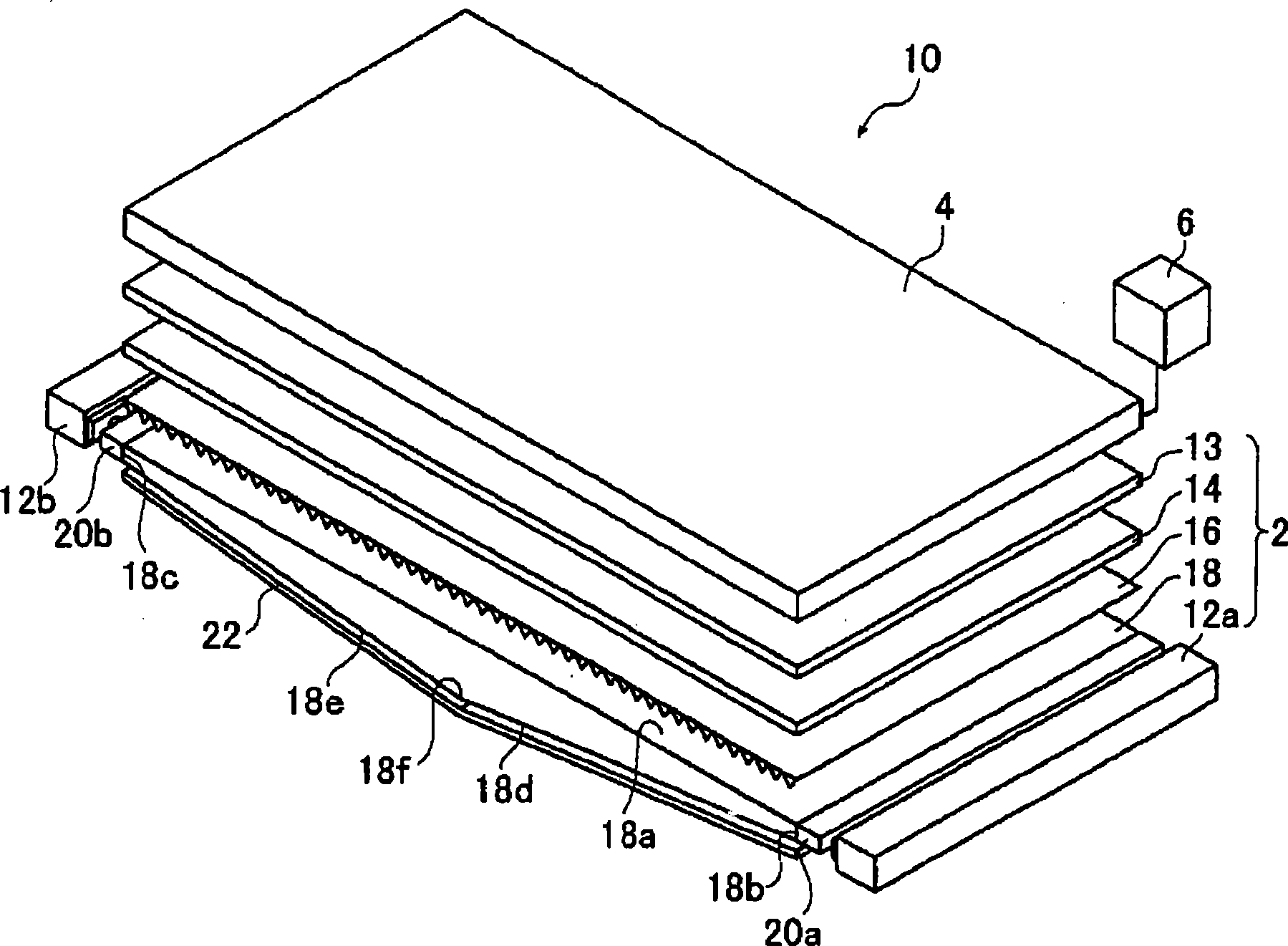
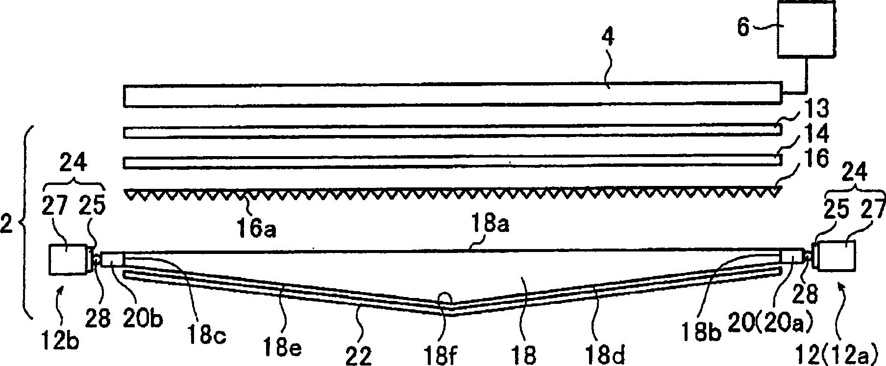
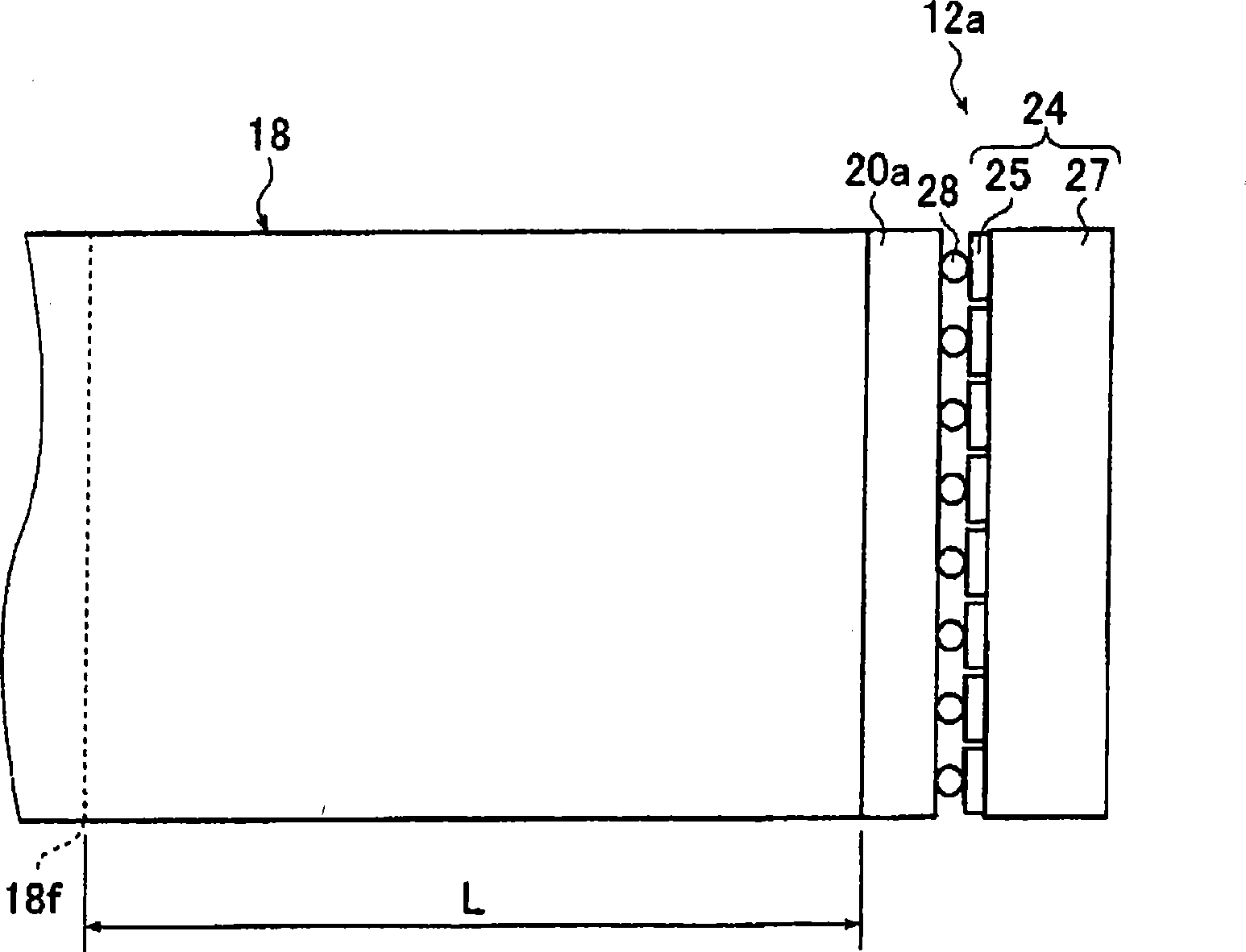
[0096] FIG. 1(A) is a schematic perspective view showing an embodiment of a liquid crystal display device equipped with an embodiment of a planar lighting device utilizing an embodiment of the light guide plate assembly of the present invention, and FIG. (A) is a schematic cross-sectional view of a liquid crystal display device. And Fig. 2 (A) is a schematic partial top view of a light guide plate and a lig...


PUM


Abstract

A light guide plate, comprising a light exiting surface and a light entering end, has a shape in which its thickness perpendicular to the light exiting surface increases gradually as it is away from the light entering end and has scattering particles scattered therein. A light guide plate assembly comprises this guide plate, and a prism sheet in which a plurality of prisms are arranged in parallel with the apex angles of the prisms arranged facing the light exiting surface. A surface illuminating device comprises a light guide plate or a light guide plate assembly, and a liquid crystal display device comprises the surface illuminating device. The scattering particles scatter light entering at the light entering end and propagating through the inside and satisfy the following expression (1) and (2), and the apex angles of the prisms of the prism sheet satisfy the following expressions (3) and (4). (F is scattered sectional area, NP is particle density, LG is length of guide plate along incident direction, KC is correction coefficient, phi is apex angle of symmetric prism, and theta1 and theta2 are two apex angles divided by perpendicular of non-symmetric prism.) 1.1<=FNPLGKC<=8.2 ---(1) 0.005<=KC<=0.1 ---(2) 55 DEG<=theta<=80 DEG ---(3) 0 DEG<= theta1<= 15 DEG and 30 DEG<= theta2<= 45 DEG ---(4).

Description

technical field [0001] The present invention relates to a light guide plate for converting light from a light source such as a point light source or a linear light source into planar light; Specifically, it relates to a light guide plate for uniformly emitting planar illumination light with a large illumination area, a light guide plate assembly capable of maximizing light utilization efficiency and front brightness, and a method using them A planar lighting device that has a large lighting area and improves in-plane uniformity to illuminate indoors and outdoors, or a planar lighting used as a backlight for liquid crystal display panels of liquid crystal display devices, advertising panels, advertising towers, billboards, etc. device and a large-screen liquid crystal display device. Background technique [0002] Conventionally, fluorescent tubes such as cold-cathode tubes and hot-cathode tubes have been used as light sources in liquid crystal display devices and planar ligh...

Claims


Application Information

Patent Timeline
Patent Type & Authority Applications(China)
IPC IPC(8): F21V8/00G09F13/04G02B6/00F21Y101/02G02F1/13357G02B5/02
Inventor 奥村高充远藤俊明
Owner FUJIFILM CORP
Why Eureka
Try Eureka