Linear constant current drive mode of LED signal lamp for automobile

A linear constant current drive and linear constant current technology, applied in the field of electric lighting, can solve problems such as increased manufacturing costs, electrical noise, and electromagnetic interference of electrical devices, and achieve constant output current, prevent damage, and avoid light decay.

Active Publication Date: 2014-01-29
HASCO VISION TECHNOLOGY CO LTD
View PDF5 Cites 0 Cited by
  • Summary
  • Abstract
  • Description
  • Claims
  • Application Information

AI Technical Summary

Problems solved by technology

[0015] But relatively speaking, the DC-DC conversion type is relatively expensive, requires a dedicated control chip and peripheral structures such as inductors and capacitors, and has high-frequency oscillation signals. From the perspective of electromagnetic compatibility, the DC-DC conversion type is prone to electrical noise. , will also generate strong electromagnetic interference to the surrounding electrical devices
[0016] Considering that in the field of LED drive control with low current, by properly arranging the connection of LED strings, the power consumption on the drop-down resistor itself is very small. If the DC-DC conversion drive circuit is used, it cannot take advantage of its high efficiency. , on the contrary, it will increase the manufacturing cost a lot, and there is also the possibility that the electrical noise will exceed the standard

Method used


Image

  • Linear constant current drive mode of LED signal lamp for automobile

Examples


Embodiment Construction

[0037] The present invention will be further described below in conjunction with the accompanying drawings.

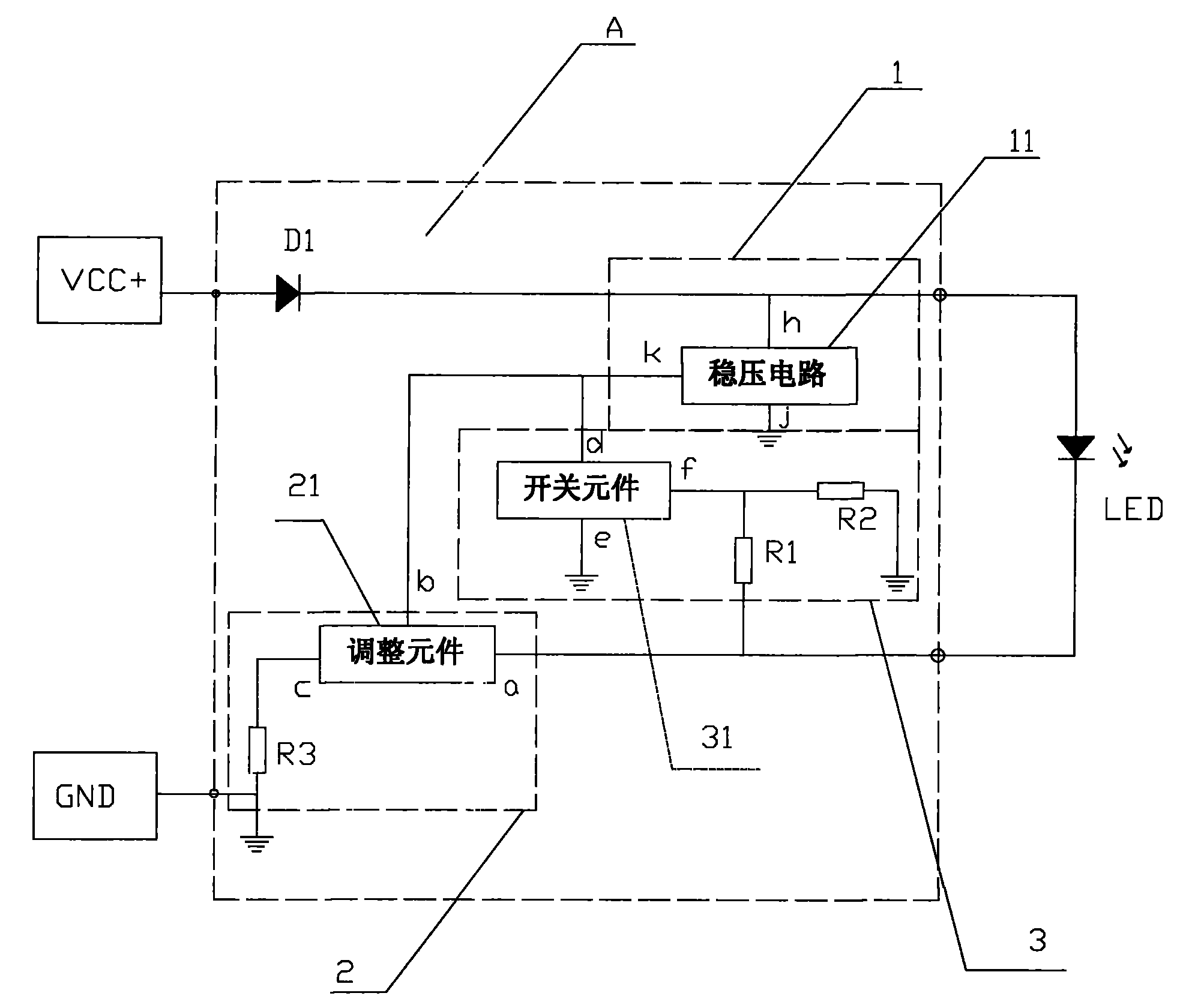
[0038] figure 1 Among them, in the technical solution described in the present invention, a linear constant current control module A is set between the DC power supply and the automotive LED signal lamp connected thereto, and provides linear constant current drive to the automotive LED signal lamp, and its linear constant current control module A It includes a voltage stabilizing unit 1, a protection unit 3 and an execution unit 2; the first input terminal of the linear constant current control module is connected to the positive power supply output terminal VCC+ of the DC power supply, and the second input terminal is grounded; the first, The second output terminal is connected to the two ends of the car LED signal light correspondingly;

[0039] Wherein, at the first input terminal of the linear constant current control module, a voltage stabilizing unit 1 is set; b...


PUM


Abstract

The invention relates to a linear constant current drive mode of an LED signal lamp for an automobile, which belongs to the field of electric illumination. The linear constant current drive mode comprises that a linear constant current control module is arranged between a direct current supply and the LED signal lamp for the automobile connected with the direct current supply and provides linear constant current drive for the LED signal lamp for the automobile, wherein the linear constant current control module comprises a voltage-stabilizing unit, a protective unit and an executing unit; and at the stage that the value of the working current of the LED signal lamp is lower than that of set current, the forward working current of an LED generates linear change following the change of input power supply voltage. After the working current of the LED reaches the set working current, the working current of the LED is set at a setting value by a constant current way; and after the value of the working current of the LED is larger than the setting value, the working current of the LED does not generate linear increase following the increase of the power supply voltage, and current outputted by a load is constant. The linear constant current drive mode has the advantages of simple current structure and low production cost, and is particularly suitable for the linear constant current drive of the LED signal lamp of a low current automobile. In addition, the linear constant current drive mode prevents heavy current from damaging the LED.

Description

technical field [0001] The invention belongs to the field of electric lighting, and in particular relates to a control method and a control device for LED lamps used in automobiles. Background technique [0002] In the mid-1980s, LEDs (Light Emitting Diodes, light-emitting diodes) began to be used in automobile central high-mounted stop lamps (CHMSL, Central High Mounted Stop Lamp). Panel backlighting generally adopts LED as a new solid-state light source. After entering the new century, with the improvement of LED power and brightness, in addition to automobile headlights, LED has fully entered the application of automobile lighting and signal systems. [0003] The biggest difference between automotive LED lamps and halogen lamps is that automotive LED lamps cannot be directly powered. Therefore, to use LEDs as lighting sources, it is necessary to solve the problem of power drive. [0004] At present, the driving circuits of automotive LED signal lights can be roughly divi...

Claims


Application Information

Patent Timeline
IPC IPC(8): H05B37/02
Inventor 夏盛
Owner HASCO VISION TECHNOLOGY CO LTD
Why Eureka
Try Eureka