Moving contact component and startup relay

A technology of moving contacts and components, applied in the direction of relays, electromagnetic relays, detailed information of electromagnetic relays, etc., can solve the problems of reduced service life, affecting service life, high cost, etc., achieve stable working performance, reduce mechanical wear, and ensure service life Effect

Inactive Publication Date: 2009-09-16
浙江致威电子科技有限公司
View PDF1 Cites 7 Cited by
  • Summary
  • Abstract
  • Description
  • Claims
  • Application Information

AI Technical Summary

Problems solved by technology

[0004] This kind of starting relay has the following disadvantages: (1) In long-term use, the moving contact piece is easy to affect the service life due to the collision when the moving and static contacts are closed; (2) the structure of the floating contact used is relatively complicated, zero Th

Method used


Image

  • Moving contact component and startup relay
  • Moving contact component and startup relay
  • Moving contact component and startup relay

Examples


Embodiment 1

[0036] (Embodiment 1, moving contact assembly)

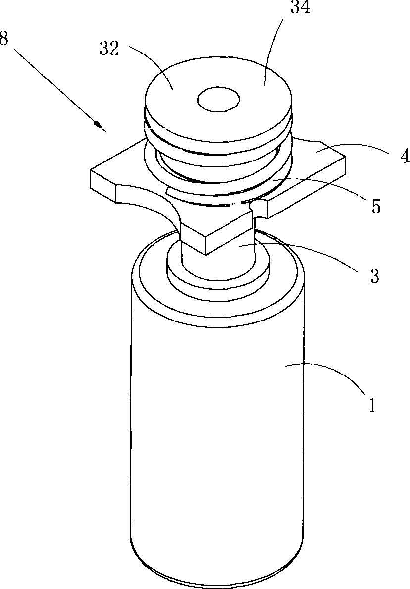
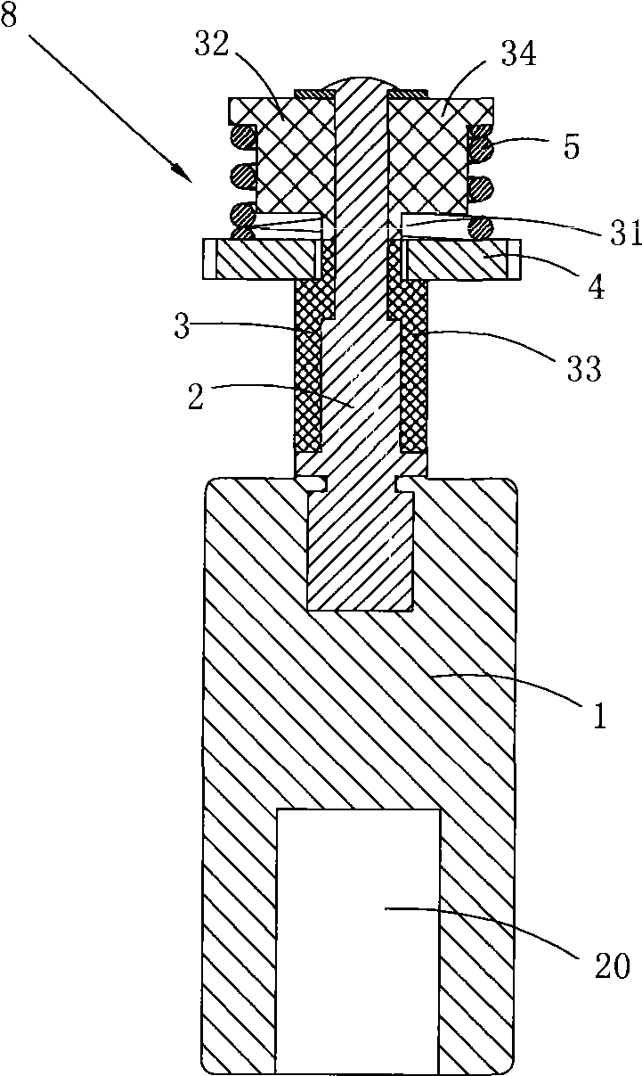
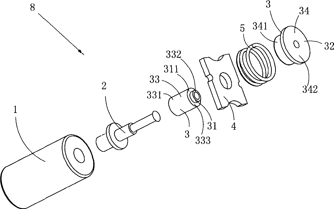
[0037] Figure 1 to Figure 3 A specific embodiment of the moving contact assembly of the present invention is shown, wherein figure 1 It is a schematic diagram of a three-dimensional structure of the moving contact assembly of the present invention, figure 2 yes figure 1 Schematic diagram of the half-section structure of the moving contact assembly shown; image 3 yes figure 1 A schematic diagram of the exploded structure of the moving contact assembly shown.

[0038] This embodiment is a moving contact assembly, see Figure 1 to Figure 3 , including a moving iron core 1, a positioning rod 2 fixedly connected to the moving iron core 1, an insulating sheath 3 sleeved on the positioning rod 2, a moving contact piece 4 sleeved on the insulating sheath 3, and a buffer Spring 5; the moving contact piece 4 and the buffer spring 5 are sequentially arranged along the direction away from the moving iron core 1; the insulating shea...

Embodiment 2

[0047] (Embodiment 2, start relay)

[0048] Figure 4 to Figure 11 A specific embodiment of the inventive starting relay is shown, wherein Figure 4 It is a schematic diagram of a three-dimensional structure of the starting relay of the present invention; Figure 5 yes Figure 4 The three-dimensional structural schematic diagram of the starting relay shown when viewed from another angle; Figure 6 yes Figure 4 The schematic diagram of the plane structure of the starting relay shown when viewed from a top view; Figure 7 yes Figure 6 Anatomical diagram along line A-A; Figure 8 yes Figure 6 Anatomical diagram along the B-B line; Figure 9 is Figure 4 A schematic diagram of a half-section structure of the start relay in the state when the coil is de-energized; Figure 10 yes Figure 4 A schematic diagram of the three-dimensional structure of the starting relay after the upper cover is removed; Figure 11 yes Figure 4 A three-dimensional structural schematic diagr...


PUM


Abstract

The invention discloses a moving contact component and a startup relay. The moving contact component comprises a moving iron core, a locating rod, an insulated jacket sleeved on the locating rod and a moving contact piece and a buffer spring sleeved on the insulated jacket, wherein the moving contact piece and the buffer spring are arranged in turn in a direction far away from the moving iron core; the insulated jacket is provided with a sliding area; and the moving contact piece can move to and fro within the sliding area under the action of outside force and the restore elastic force of the buffer spring. The startup relay comprises a shell, a coil component, a moving contact component of the structure, a fixed contact component and a restore spring providing the restore elastic force for the moving contact component. The moving contact piece and two fixed contact pieces can be closed in the process that the moving contact piece moves along with the moving iron core. The moving contact component and the startup relay have the advantages that the moving contact piece is directly arranged on the moving iron core, so that the overall structure is integrated and the installation and the maintenance is convenient; and the buffer spring effectively reduces abrasion caused by collision when the moving contact piece and the fixed contact pieces are closed, and ensures the service life of the moving contact piece.

Description

technical field [0001] The invention belongs to the technical field of relay structure design, and in particular relates to a moving contact assembly and a starting relay. Background technique [0002] The control circuit of the starter motor of a diesel locomotive often uses a starter relay (also called an intermediate relay), which is used to control the on-off of a large-current circuit with a small current. [0003] Patent document CN201126795Y discloses an automobile starter motor intermediate relay, which includes a coil magnetic circuit mechanism arranged in the casing, an actuator driven by the coil magnetic circuit mechanism, and a pair of connecting bolts fixed on the switch cover; Head pillar, one end of which is fixedly connected to the iron core in the coil magnetic circuit mechanism, the other end passes through the yoke plate in the coil magnetic circuit mechanism and installs the moving contact, and is connected to the switch cover through a reset compression...

Claims


Application Information

Patent Timeline
IPC IPC(8): H01H50/54H01H50/64H01H9/30
Inventor 赵顺荣
Owner 浙江致威电子科技有限公司
Why Eureka
Try Eureka