Common rail electronic control jet apparatus

An injector and common rail technology, which is applied in fuel injection devices, special fuel injection devices, fuel injection devices with wear-reducing measures, etc., can solve the problems of multiple control links, limited electromagnetic force of electromagnets, and high manufacturing costs. Achieve the effect of high energy utilization rate, less control links and low manufacturing cost

Active Publication Date: 2009-09-23
浙江朗杰电子有限公司
View PDF0 Cites 22 Cited by
  • Summary
  • Abstract
  • Description
  • Claims
  • Application Information

AI Technical Summary

Problems solved by technology

Disadvantages of this type of technology: 1. There are many control links. The electromagnetic force is first converted to the displacement of the solenoid valve spool, then converted to the pressure of the control room, and then converted to the displacement of the needle valve. Many control links make it difficult to control the size chain, and the manufacturing cost is high and reliable. 2. There are many dynamic sealing links, and the hydraulic piston or the outer cylindrical surface of the needle valve have dynamic sealing requirements, resulting in leakage loss and jammed fault sources; 3. The solenoid valve will discharge during the process of releasing the pressure in the control room. A considerable proportion of high-pressure fuel, plus the leakage loss of the dynamic sealing link, the energy utilization rate is low; 4. The injector must have an oil return port to collect the oil returned from the control room and the fuel leaked by the dynamic seal, and the pipeline layout is complicated
However, due to the limited electromagnetic force of the electromagnet, the electronically controlled injector using this working principle is only suitable for occasions with low injection pressure (less than 120bar)
Cannot be used in diesel fuel injection systems

Method used


Image

  • Common rail electronic control jet apparatus
  • Common rail electronic control jet apparatus

Examples


Embodiment Construction

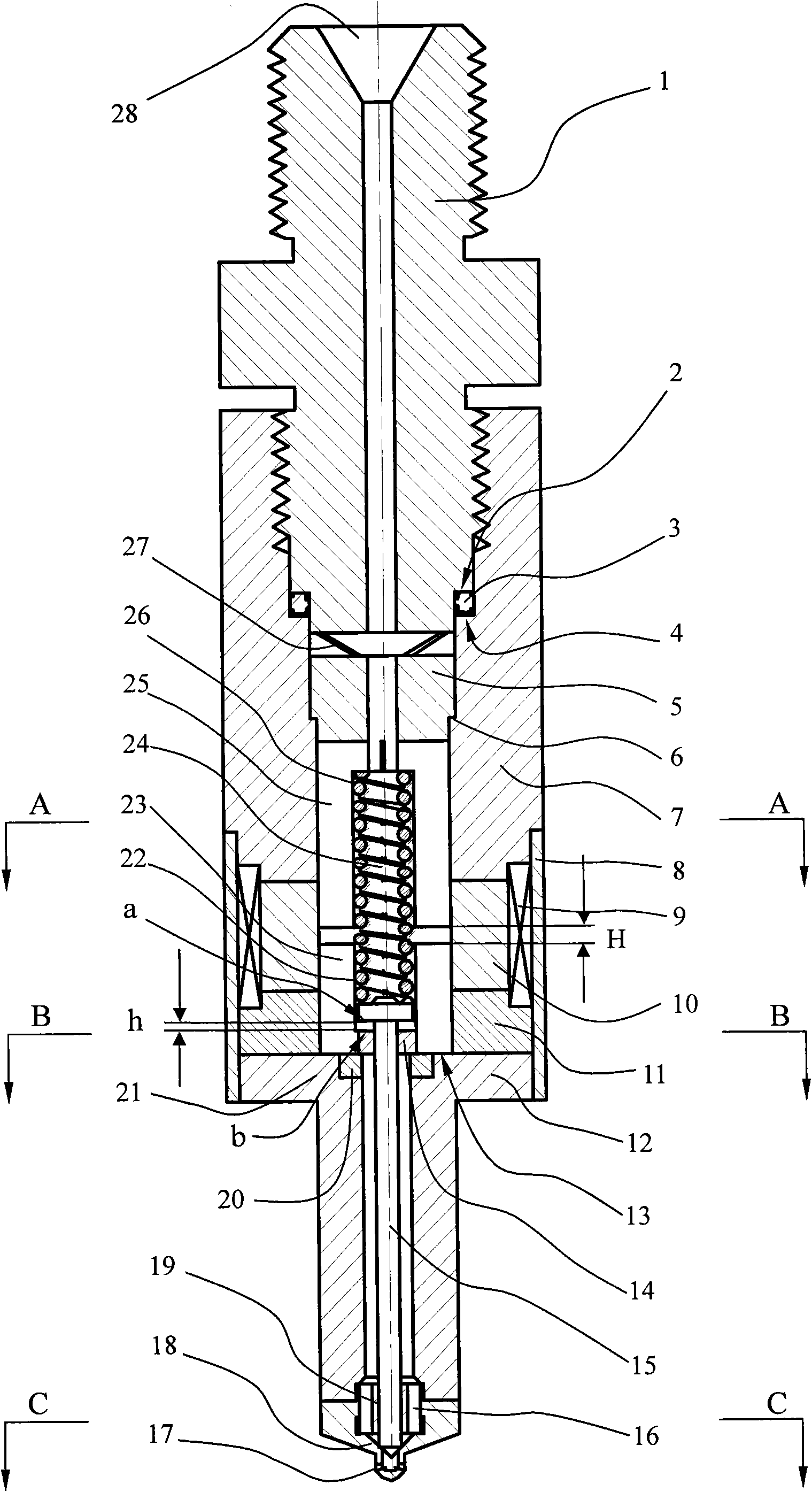
[0021] The structure and principle of the common rail electronically controlled injector will be described in detail below in conjunction with the attached drawings:

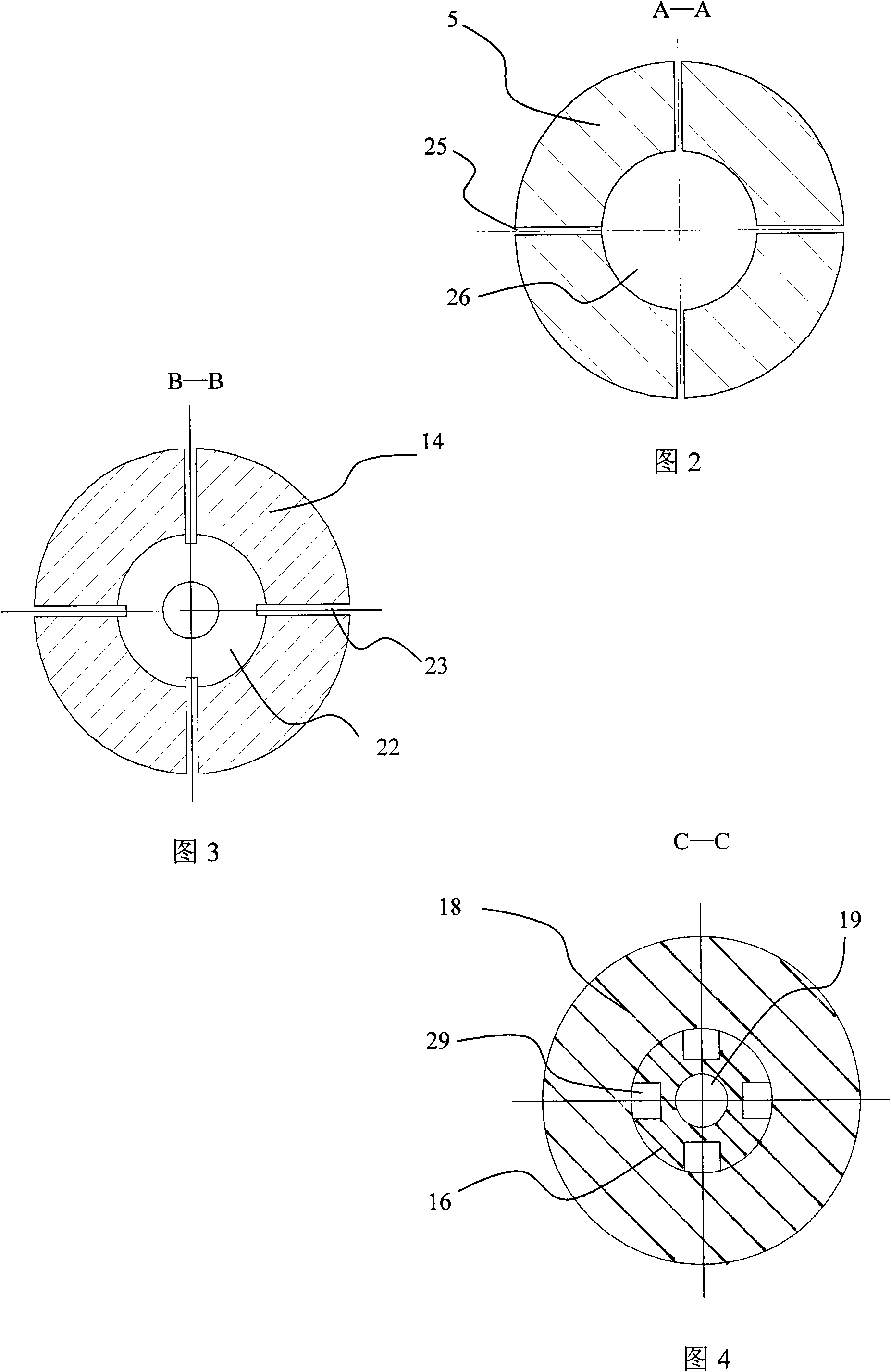
[0022] Such as figure 1 As shown, the common rail electronically controlled injector includes: an oil inlet joint 1, an oil inlet 28 located at the outer end of the oil inlet joint 1, an electromagnet device, a nozzle body 12, a needle valve 15, a valve seat 18 and an injection hole 17. Described electromagnet device comprises a static iron core 5, a moving iron core 14 and a coil 9, the working gap H between the static iron core 5 and the moving iron core 14,

[0023] The moving iron core 14 and the needle valve 15 are flexibly connected in the axial direction. When the electromagnet device is powered off and reset, the axial distance between the moving iron core 14 and the needle valve 15 is h. After the electromagnet device is energized, the moving iron core The iron core 14 approaches the needle valve 15 fi...


PUM


Abstract

The invention relates to a common rail electronic control jet apparatus, belonging to technology of an electronic control fuel injection system. The controller comprises an oil inlet joint, an oil inlet, an electromagnet device, a nozzle body, a needle valve, a valve seat and a jet orifice; wherein, the electromagnet device includes a static iron core, a moving iron core and a coil, and a working clearance H exists between the static iron core and the moving iron core along the axial direction; the moving iron core is movably connected with the needle valve along the axial direction; the controller also comprises a compression spring acting on the needle valve, a force application mechanism acting on the moving iron core and a blocking mechanism used for providing axial anti-thrust when the moving iron core resets. The common rail electronic control jet apparatus has the advantages of low manufacturing cost, good reliability and low drive energy.

Description

technical field [0001] The invention relates to a common rail electronically controlled injector, in particular to a common rail electronically controlled injector used in a common rail electronically controlled fuel injection system of a compression ignition engine (diesel engine). Background technique [0002] The function of the common rail electronically controlled injector is to control the start and end of injector injection by using pulse electric signals. Existing technologies, such as the CR system of BOSCH Company, the ECD-U2 system of Denso Corporation of Japan, the unijet system of FIAT Group of Italy, and the LDCR system of DELPHIDIESEL SYSTEMS of the United Kingdom, have common rail type electronically controlled injectors. : There is a solenoid valve and a control room controlled by the solenoid valve. The electromagnetic force first controls the switching action of a solenoid valve, changes the pressure of the control room, thereby changes the hydraulic press...

Claims


Application Information

Patent Timeline
Patent Type & Authority Applications(China)
IPC IPC(8): F02M51/06
CPCF02M2200/02F02M2200/9038F02M2200/08F02M51/0685F02M51/0671
Inventor 汪洋张晓朱涛盖超田青云何方
Owner 浙江朗杰电子有限公司
Why Eureka
Try Eureka