Al technical title is built by PatSnap Al team. It summarizes the technical point description of the patent document.
A mixer and frame technology, applied in mixers, mixers with rotating containers, dissolving, etc., can solve problems such as unsatisfactory mixing effect, inability to mix materials evenly, easy to generate air bubbles, etc., so as to eliminate the need to clean the mixing paddle The complicated process, the effect is ideal, and the effect of eliminating air bubbles
Inactive Publication Date: 2011-06-29
佛山市恒之芯复合材料有限公司
View PDF0 Cites 1 Cited by
Summary
Abstract
Description
Claims
Application Information
AI Technical Summary
This helps you quickly interpret patents by identifying the three key elements:
Problems solved by technology
Method used
Benefits of technology
Problems solved by technology
[0002] At present, the common mixers on the market for mixing multi-component solid-solid phase, solid-liquid phase, and liquid-liquid phase materials, such as reaction, dispersion, dissolution, conditioning, etc., are usually equipped with stirring paddles. Drive the stirring blade to rotate in the material barrel to mix and stir the materials in the material barrel. Since most materials have high viscosity, in order to mix and stir the materials evenly, the structure design of the stirring blade is more complicated. After stirring, it will There are a lot of materials attached to the surface of the mixing paddle, which brings inconvenience to cleaning, and it is difficult for the paddle to stir the material on the edge of the material bucket during the mixing process, which brings pollution to the material and cannot mix the material well; In addition, the material stirred by the stirring paddle is prone to air bubbles, and the stirring effect is not very satisfactory. In view of the above shortcomings, it is necessary to make improvements
Method used
Image
Click on the blue label to locate the original text in one second.
Reading with bidirectional positioning of images and text.
Examples
Embodiment Construction
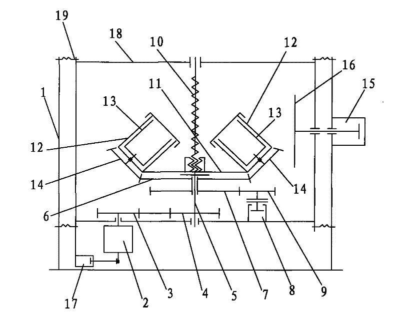
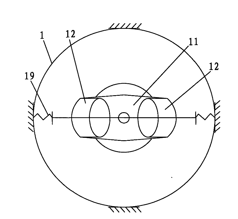
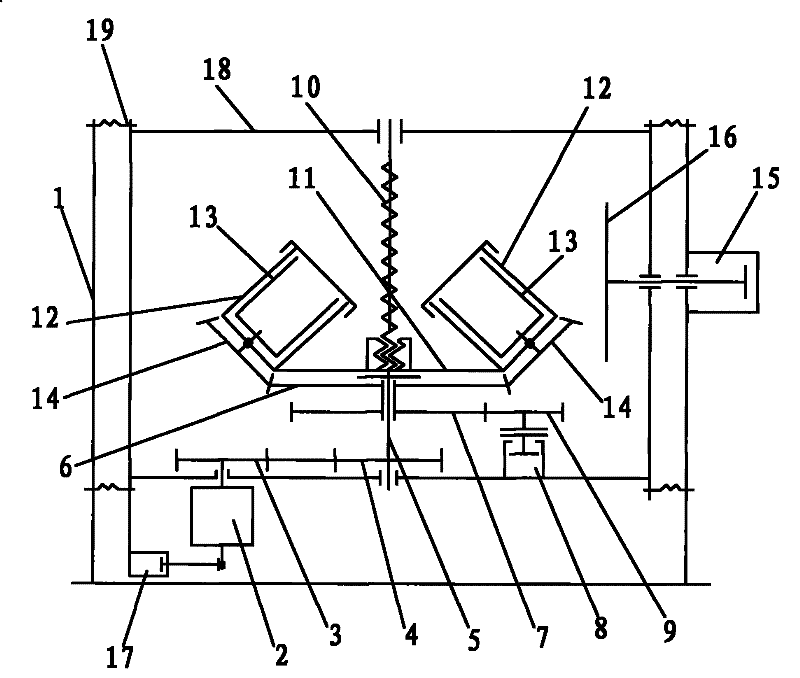
[0014] refer to figure 1 , figure 2 , a mixer, comprising a frame 1, the frame 1 is provided with a motor 2, on the rotating shaft of the motor 2 is connected with a main synchronous pulley 3, and the main synchronous pulley 3 passes through a synchronous belt and a slave synchronous belt The pulley 4 is connected, and the main shaft 5 passes through the shaft center of the synchronous pulley 4 and is socketed with it. The upper and lower gears 6 and 7 which are integrally connected are also set on the main shaft 5. The frame 1 is provided with a pneumatic clutch 8 , there is a speed change gear 9 set on the connecting shaft of the pneumatic clutch 8, the speed change gear 9 is meshed with the lower gear 7, the surface of the main shaft 5 is located above the upper gear 6 and is provided with a thread 10, and a receiving platform 11 passes through it The casing with internal thread is connected to the thread 10 on the main shaft 5, and the left and right sides of the receivi...
PUM
Abstract
The invention discloses a stirrer, which comprises a machine frame, wherein the machine frame is provided with a motor which is connected with a driving synchronous belt wheel through a driven synchronous belt wheel and a synchronous belt and has a main shaft which is connected with the shaft sleeve of the driven synchronous belt wheel, and the main shaft is also sleeved with integrally connectedupper and lower gears; the machine frame is also provided with a pneumatic clutch and a transmission gear meshed with the lower gear, the surface of the main shaft is provided with threads, a socket platform is sleeved on the threads, a revolution tank and a rotation tank are fixed on the left and right sides of the socket platform respectively, the lower part of the rotation tank is connected with a pinion through a connecting shaft, and the pinion is meshed with the upper gear; and the machine frame is provided with an air cylinder and the front end of the air cylinder is connected with a baffle plate. The stirrer is reasonable in structure and convenient in use and can uniformly stir materials, avoid generating air bubbles, eliminate air bubbles and be used in fields of electronics, chemical, light manufacturing, food, medicine, building materials, farm chemical and the like for mixing, dispersing and other processing of materials.
Description
technical field [0001] The present invention relates to a mixing equipment used in electronics, chemical industry, light industry, food, pharmacy, building materials, pesticides and other industries, especially a kind of mixing equipment for multi-component solid-solid phase, solid-liquid phase, liquid-liquid phase materials Mixer for mixing, reaction, dispersion, dissolution, tempering and other processing. Background technique [0002] At present, the common mixers on the market for mixing multi-component solid-solid phase, solid-liquid phase, and liquid-liquid phase materials, such as reaction, dispersion, dissolution, conditioning, etc., are usually equipped with stirring paddles. Drive the stirring blade to rotate in the material barrel to mix and stir the materials in the material barrel. Because most of the materials have high viscosity, in order to mix and stir the materials evenly, the structure design of the stirring blade is more complicated. After stirring, it wi...
Claims
Application Information
Patent Timeline
Application Date:The date an application was filed.
Publication Date:The date a patent or application was officially published.
First Publication Date:The earliest publication date of a patent with the same application number.
Issue Date:Publication date of the patent grant document.
PCT Entry Date:The Entry date of PCT National Phase.
Estimated Expiry Date:The statutory expiry date of a patent right according to the Patent Law, and it is the longest term of protection that the patent right can achieve without the termination of the patent right due to other reasons(Term extension factor has been taken into account ).
Invalid Date:Actual expiry date is based on effective date or publication date of legal transaction data of invalid patent.