Cavity splitting device for injection forming mould

An injection molding and mold technology, applied in the field of injection molding molds, can solve the problems of wasting manpower and time costs, affecting production efficiency, etc., and achieve the effect of improving production efficiency and saving time for cavity division

Inactive Publication Date: 2009-12-02
HONG FU JIN PRECISION IND (SHENZHEN) CO LTD +1
View PDF0 Cites 7 Cited by
  • Summary
  • Abstract
  • Description
  • Claims
  • Application Information

AI Technical Summary

Problems solved by technology

[0003] When the mold has multiple cavities in one mold, since the products fall directly into the product basket, if you want to distinguish different products in each cavity or if the

Method used


Image

  • Cavity splitting device for injection forming mould
  • Cavity splitting device for injection forming mould
  • Cavity splitting device for injection forming mould

Examples


Embodiment Construction

[0010] The present invention will be described in detail below in conjunction with the accompanying drawings.

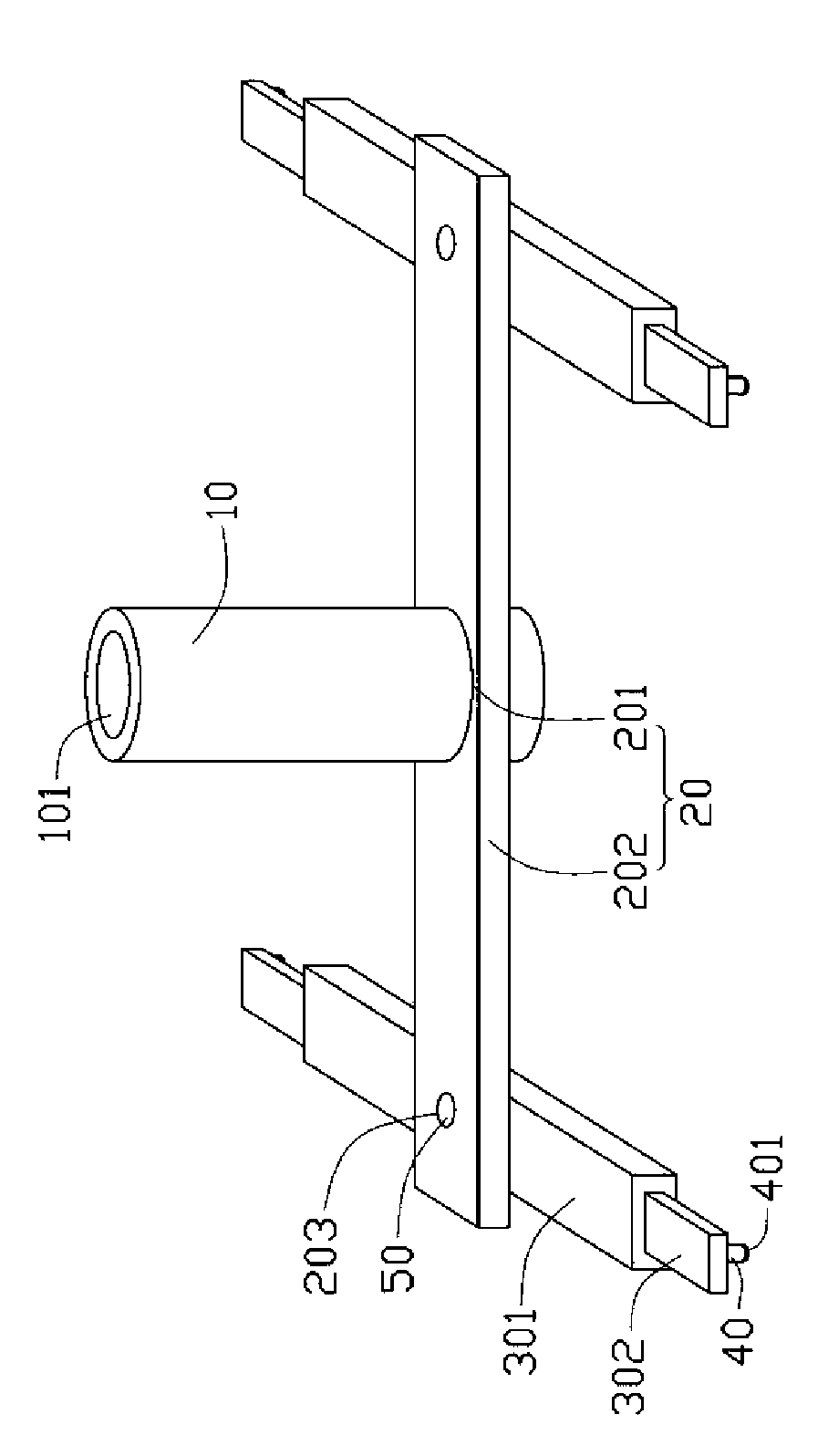
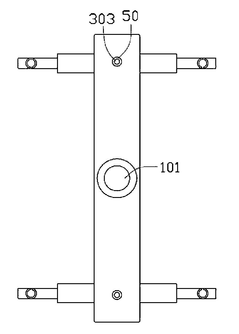
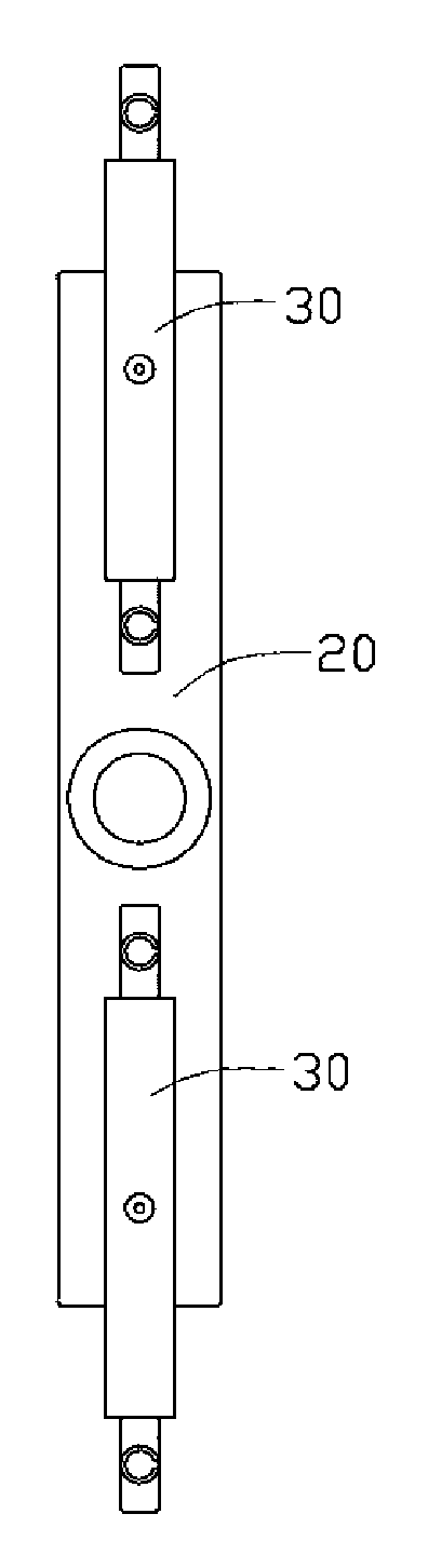
[0011] see figure 1 and figure 2 , the injection mold cavity dividing device includes a vertical bar 10, a horizontal bar 20 whose middle part is vertically fixed on the vertical bar 10, and two telescopic bars 30 respectively rotatably arranged at both ends of the horizontal bar 20, And a plurality of adsorption devices 40 respectively located at the ends of the telescopic rods 30 .

[0012] The bottom end of the vertical rod 10 defines a cavity 101 for accommodating the sprue head of the injection mold.

[0013] The horizontal bar 20 has a sleeve portion 201 and a rod portion 202 extending along both sides of the sleeve portion 201, the sleeve portion 201 is sleeved on the vertical rod 10, and the rod portion 202 is opposite to the Each end defines a first through hole 203 .

[0014] The telescopic rod 30 has a hollow sleeve rod 301 , and two ends of the hollo...


PUM


Abstract

The invention relates to a cavity splitting device for an injection forming mould, which comprises a vertical rod, a cross rod of which the middle part is vertically fixed on the vertical rod, two telescopic rods which are respectively and rotatably arranged at two ends of the cross rod, and a plurality of adsorption devices which are positioned at the end part of the telescopic rod. The cavity splitting device for the injection forming mould adopts the structures with the vertical rod, the cross rod and the telescopic rod to adapt to moulds with different mould cavities; and meanwhile, the adsorption devices can split cavities and respectively split products in the mould cavities to corresponding product baskets, thereby omitting the procedures of distinguishing the products in the mouldcavities by artificial visual inspection, easily knowing the products in which mould cavities have flaws, correcting corresponding mould cavities, saving cavity splitting time, and improving the production efficiency. The cavity splitting device can save the time for splitting the cavities and labor force cost, and improve the production efficiency.

Description

technical field [0001] The invention relates to an injection mold. Background technique [0002] Injection molding molds need to take out the molded product from the mold cavity after the injection material is cooled and formed. In the existing injection molding mold, after the injection material is cooled and formed, a mechanical arm is generally used to separate the material head from the product and then take it out, so that the product Drop directly into the product basket. [0003] When the mold has multiple cavities in one mold, since the products fall directly into the product basket, if you want to distinguish different products in each cavity or if there is a defect in a certain cavity, you need to go through manual visual inspection, which will inevitably cause Great waste of manpower and time costs, affecting production efficiency. Contents of the invention [0004] In view of this, it is necessary to provide an injection molding mold cavity dividing device, w...

Claims


Application Information

Patent Timeline
IPC IPC(8): B29C45/40
Inventor 周建宏
Owner HONG FU JIN PRECISION IND (SHENZHEN) CO LTD
Why Eureka
Try Eureka