

Bearing device for wheel
A bearing device and wheel technology, applied in the directions of bearings, axles, wheels, etc., can solve the problem of easy loosening of bolts, and achieve the effect of improving strength and not producing abnormal noise.
- Summary
- Abstract
- Description
- Claims
- Application Information
AI Technical Summary
Problems solved by technology
Method used
Image

Examples
Embodiment Construction
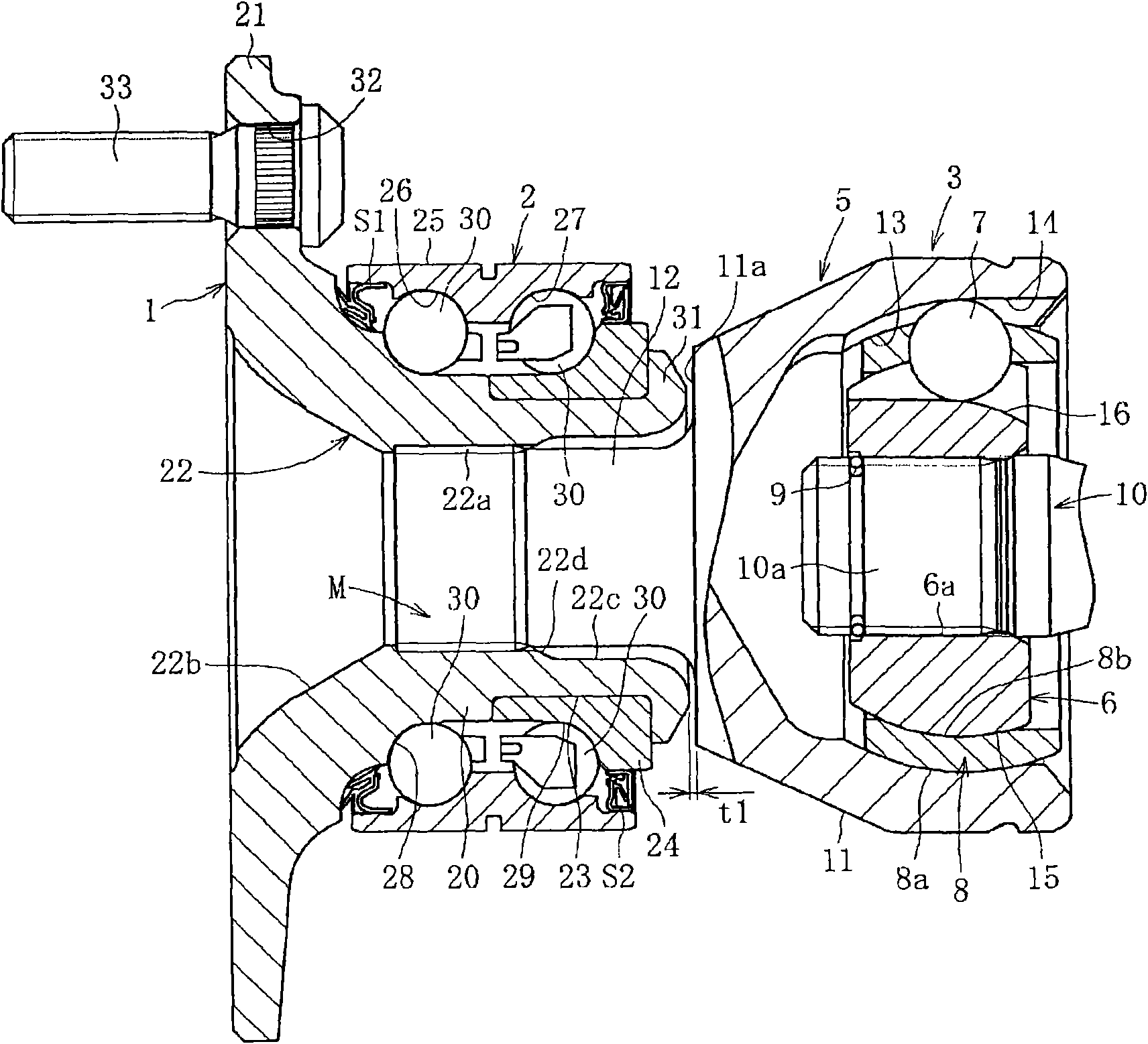
[0099] Below, refer to figure 1 ~ Figure 21 illustrates an embodiment of the present invention. figure 1 A bearing device for a wheel according to the first embodiment is shown, and the bearing device for a wheel is formed by integrally integrating a hub 1 , a multi-row rolling bearing 2 and a constant velocity universal joint 3 .
[0100] The constant velocity universal joint 3 includes an outer ring 5 as an outer joint member, an inner ring 6 as an inner joint member disposed inside the outer ring 5 , and a plurality of joints sandwiched between the outer ring 5 and the inner ring 6 to transmit torque. The balls 7 and the cage 8 holding the balls 7 sandwiched between the outer ring 5 and the inner ring 6 are composed as main components. The inner ring 6 is spline-fitted by press-fitting the end portion 10 a of the shaft 10 into the inner diameter 6 a of the shaft hole, and coupled to the shaft 10 so that torque can be transmitted. In addition, a stop ring 9 for preventin...
PUM
 Abstract
Description
Claims
Application Information