Self-adaptive power matching circuit of fluorescent lamp and method

A matching circuit and adaptive technology, applied in the field of adaptive power matching circuit of fluorescent lamps, to avoid waste and high cost of use

CN101707848AInactive Publication Date: 2010-05-12OCEANS KING LIGHTING SCI&TECH CO LTD +1
0 Cites 1 Cited by

Patent Information

Authority / Receiving Office
CN · China
Patent Type
Applications(China)
Current Assignee / Owner
Publication Date
2010-05-12
Estimated Expiration
Not applicable · inactive patent

Smart Images

  • Figure 1
    Figure 1
  • Figure 2
    Figure 2
  • Figure 3
    Figure 3
Patent Text Reader

Abstract

The invention relates to a self-adaptive power matching circuit of a fluorescent lamp, which comprises a micro control unit (MCU), a driving circuit and a fluorescent lamp tube, and also comprises a detection circuit connected with the fluorescent lamp tube for acquiring a current or voltage signal of the fluorescent lamp tube. The MCU comprises a feedback detection module, a power matching module and a frequency modulation control module; the feedback detection module receives the current or voltage signal output by the detection circuit, and converts an analog signal into a digital signal; the power matching module receives the signal and performs power matching processing, and detects the starting frequency of the fluorescent lamp tube; and the frequency modulation control module outputs pulse width modulation wave corresponding to the installed fluorescent lamp tube according to the starting frequency, and enables the fluorescent lamp tube to emit light normally through the driving circuit. The invention also relates to a self-adaptive power matching method for the fluorescent lamp. Through the circuit and the method, the ballast can adapt to a plurality of lamp tubes with different power, and the waste and high use-cost caused by replacing the ballast due to replacing the fluorescent lamp tube are avoided.
Need to check novelty before this filing date? Find Prior Art

Description

technical field

[0001] The invention relates to a ballast circuit and method applied to fluorescent lamps, more specifically, to an adaptive power matching circuit and method for fluorescent lamps. Background technique

[0002] Current ballast circuits for fluorescent lamps such as figure 1 As shown, it includes a dimming chip 10 , a driving circuit 20 , and a fluorescent tube 30 . The dimming chip 10 outputs a fixed pulse width modulation wave to the drive circuit 20, and the drive circuit 20 inverts the DC voltage into a high-frequency AC voltage output required by the fluorescent tube 30 to drive the fluorescent tube 30 to realize lighting. Therefore, a ballast can only output a pulse width modulated wave with a fixed frequency to light a fluorescent tube of corresponding power. If the lamp tube with different power is replaced, the starting frequency of the fluorescent tube will change, and the ordinary ballast circuit cannot automatically identify it, so it cannot out...

Examples

Embodiment Construction

[0014] The present invention will be further described below in conjunction with the accompanying drawings.

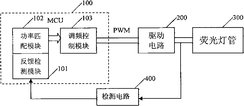
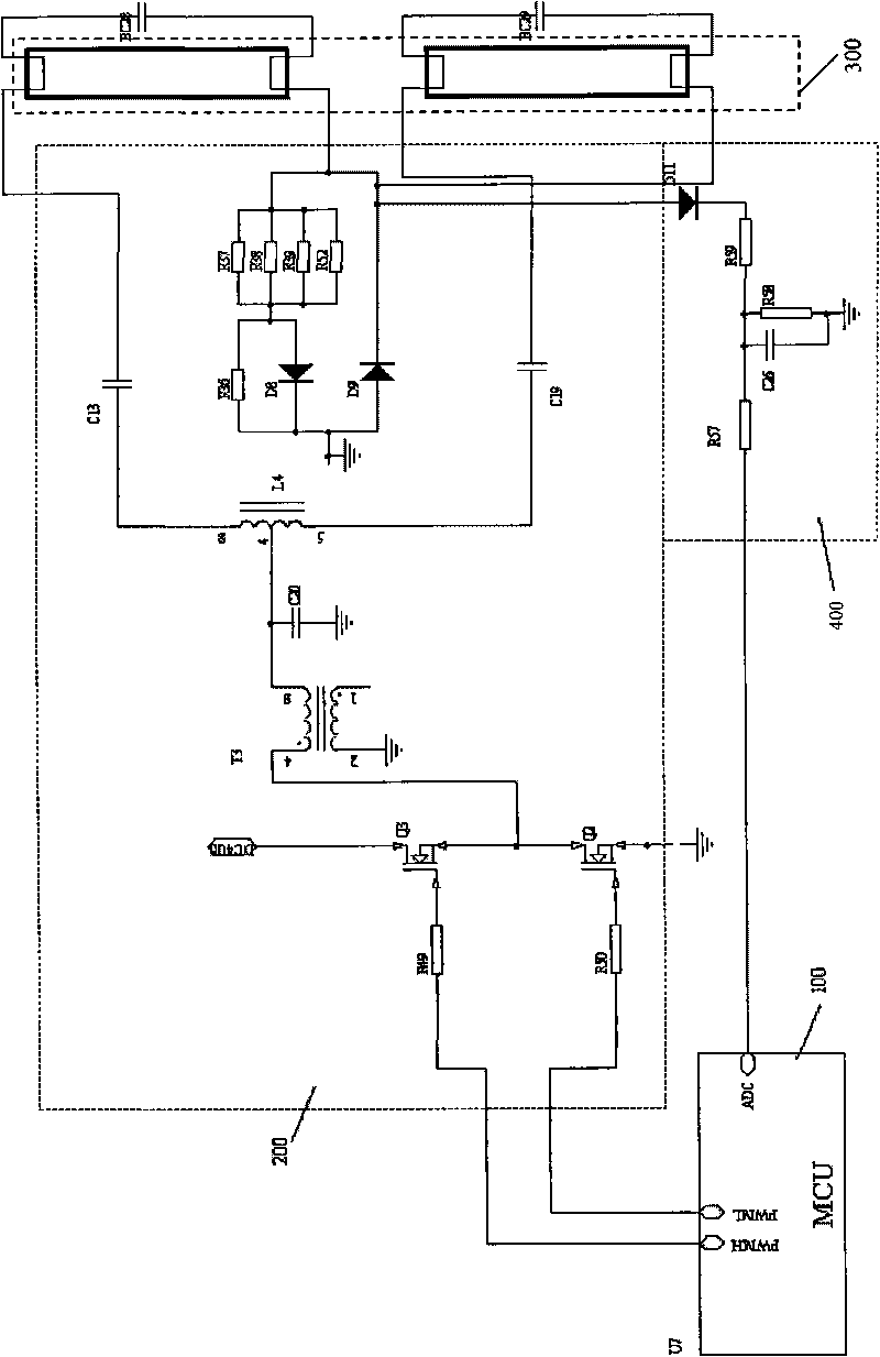
[0015] figure 2 It is a structural schematic diagram of an adaptive power matching circuit for a fluorescent lamp in the present invention. The circuit is composed of MCU100 , drive circuit 200 , fluorescent tube 300 and detection circuit 400 . Wherein the detection circuit 400 is used to collect the voltage or current signal of the fluorescent lamp 300, and output it after RC filtering; Or the voltage analog signal is converted into a digital signal and output. The power matching module 102 performs power matching processing on the digital signal output by the feedback detection module 101 to detect the starting frequency of the fluorescent lamp 300. The frequency modulation control module 103 outputs the installed fluorescent lamp according to the starting frequency. tube corresponding to the pulse width modulated wave. The driving circuit 200 converts the DC vol...