Alternating current (AC) converter for converting high voltage to low voltage

A technology of AC converter and high-frequency transformer, which is applied in the direction of converting AC power input into AC power output, output power conversion device, electrical components, etc. Functional defects and other problems, to achieve the effect of novel design concept, easy implementation and simple structure

Inactive Publication Date: 2011-01-19
SHANGHAI JIAO TONG UNIV
View PDF5 Cites 19 Cited by
  • Summary
  • Abstract
  • Description
  • Claims
  • Application Information

AI Technical Summary

Problems solved by technology

[0004] However, after careful analysis, there are some deficiencies in the technology involved in the above documents, such as complex circuit structure, high difficulty in control, difficult to implement, complex power factor control on the grid side, and various indicators other than technology such as efficiency, reliability, and cost. , volume and other indicators are difficult to improve
[0005] Based on the results of literature search and novelty search, so far, the development of power electronic transformers is still in the initial stage, and the circuit topology and control algorithm are still in the stage of using the existing basic converter topology combination and control algorithm, which is characterized by complex topology and cumbersome control. Functional defects, such as high cost, large size and low reliability

Method used


Image

  • Alternating current (AC) converter for converting high voltage to low voltage
  • Alternating current (AC) converter for converting high voltage to low voltage

Examples


Embodiment Construction

[0015] The embodiments of the present invention are described in detail below. This embodiment is implemented on the premise of the technical solution of the present invention, and detailed implementation methods and specific operating procedures are provided, but the protection scope of the present invention is not limited to the following implementation example.

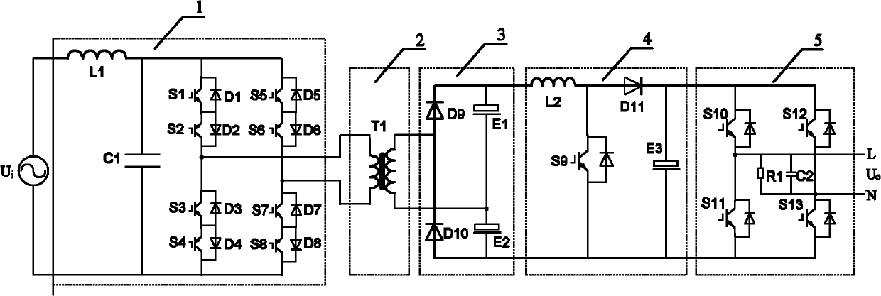
[0016] Such as figure 1 As shown, this embodiment includes: AC chopper circuit 1, high frequency transformer circuit 2, rectification filter circuit 3, waveform conversion circuit 4, power frequency inverter circuit 5, wherein: AC chopper circuit 1 will input high voltage power frequency AC The voltage is converted into a high-frequency pulse high-voltage AC voltage and output to the high-frequency transformer circuit 2, and the high-frequency transformer circuit 2 converts the high-frequency pulse high-voltage AC voltage into a high-frequency pulse low-voltage AC voltage and outputs it to the rectifier filter circ...


PUM


Abstract

The invention relates to an alternating current (AC) converter for converting high voltage to low voltage in the field of power electronics. The converter comprises an AC chopper circuit, a high-frequency transformer circuit, a rectifier and filter circuit, a waveform conversion circuit and a working frequency inversion circuit which are sequentially connected in series, wherein the AC chopper circuit is used for converting input high-voltage working frequency AC voltage into high-frequency impulse high-voltage AC voltage and outputting the converted voltage to the high-frequency transformer circuit; the high-frequency transformer circuit is used for converting high-frequency impulse high-voltage AC voltage into full wave direct current (DC) voltage and outputting the full wave DC voltageto the rectifier and filter circuit; the rectifier and filter circuit is used for converting the high-frequency impulse low-voltage AC voltage into full wave DC voltage and outputting the full wave DC voltage to the waveform conversion circuit; the waveform conversion circuit is used for boosting the full wave DC voltage, adding input current to the full wave DC voltage and then outputting the combined voltage and current to the working frequency inversion circuit; and the working frequency inversion circuit is used for inverting the DC voltage into working frequency AC sine wave voltage or AC square wave voltage and outputting the inverted voltage. The converter is an AC-AC conversion circuit which has the advantages of small volume, light weight, high efficiency, low cost, simple designand high reliability and can run with a unit power factor.

Description

technical field [0001] The invention relates to a device in the technical field of power electronics, in particular to a high-voltage to low-voltage AC converter with a power factor close to 1. Background technique [0002] The traditional AC-AC converter usually uses an AC transformer, whose output voltage is determined by the transformation ratio of the primary coil and the secondary coil, and it is difficult to obtain an arbitrary voltage value. And because it mainly adopts copper and iron as the main materials, it is bulky and very heavy. In addition, when this kind of AC transformer has a non-resistive load, the current distortion is serious, and the power factor is very low, which causes pollution to the power grid. Power electronic transformers are an alternative product of power transformers, which are receiving attention and development, and can be connected to high-voltage or low-voltage AC high-frequency power grids. Power electronic transformers have many probl...

Claims


Application Information

Patent Timeline
Patent Type & Authority Applications(China)
IPC IPC(8): H02M5/458
Inventor 杨喜军张永鑫田书欣钟莉娟
Owner SHANGHAI JIAO TONG UNIV
Why Eureka
Try Eureka