Relay device, communication system, and relay method

A technology of a relay device and a receiving device, applied in transmission systems, wireless communications, baseband systems, etc., can solve the problems of reduced frequency utilization efficiency, inability to communicate, time and cost required, and achieve improved cell throughput and expanded coverage. area effect

Inactive Publication Date: 2011-05-11
SHARP KK
View PDF5 Cites 0 Cited by
  • Summary
  • Abstract
  • Description
  • Claims
  • Application Information

AI Technical Summary

Problems solved by technology

[0013] However, it takes time and cost to replace facilities such as base stations with facilities that also support 3.9G and 4G, so not only mobile terminals but also base stations must consider the mixed existence of base stations of different generations
In addition, when installing a new base station for 3.9G in the future, building a base station that also supports 2G in consideration of this situation will require cost.
[0014] Moreover, since the new mobile communication methods of the 3.9G and 4G generations are superior to 3G in terms of frequency utilization efficiency, it is better to use the new generation of communication methods for communication as much as possible. However, in the communication between the base station and the mobile station, in the base station or If any of the mobile stations does not support the next-generation communication method, communication cannot be performed
And, for example, when the mobile station only supports 3G and the relay station and base station support not only 3G but also 3.5G and 3.9G, it is better to use 3.9G, which has the highest frequency utilization efficiency among the corresponding transmission methods, for communication between the relay station and the base station. Since the 3G transmission method is used for transmission under the current consideration method, the frequency utilization efficiency decreases

Method used


Image

  • Relay device, communication system, and relay method
  • Relay device, communication system, and relay method
  • Relay device, communication system, and relay method

Examples


no. 1 Embodiment approach

[0049] In the first embodiment, a relay device and a relay method applied to a communication system consisting of a transmitting device (mobile station) compatible only with 3G and a receiving device (base station) compatible with 3G and 3.9G will be described. constitute.

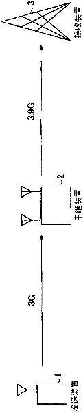
[0050] figure 1 It is a diagram showing a schematic configuration of the communication system according to the first embodiment. First, before performing data communication, the transmission device 1 notifies the relay device 2 that a signal is transmitted according to the 3G transmission method. Furthermore, the receiving device 3 also notifies the relay device 2 in advance that 3G and 3.9G demodulation is possible. Since the transmission device 1 notifies the relay device 2 of the transmission of the signal according to the 3G transmission method, as in figure 1 As shown, the transmission is performed to the relay device 2 according to the 3G transmission method. The relay device 2 receives the sig...

no. 2 Embodiment approach

[0073] In the second embodiment, a relay device and a relay method applied to a communication system consisting of a transmission device (mobile station) compatible only with 3.9G and a 4G network compatible with Dynamic Spectrum Control (DSC) will be described. The receiver device (base station device) configuration.

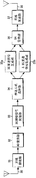
[0074] Figure 9 is a diagram showing a schematic configuration of a transmission device. First, before performing data communication, the transmitting device notifies the relay device that the signal of 3.9G is transmitted. Furthermore, the receiving device also notifies the relay device in advance that DSC demodulation is possible. exist Figure 9 , the information bit sequence is input to the 3.9G transmission signal generation unit 91. The 3.9G transmission signal generation unit 91 is used in the first embodiment Figure 5 The structure of the description is the same. The signal sequence output from the 3.9G transmission signal generation unit 91 is i...


PUM


Abstract

The coverage area of a transmission device is expanded by relaying, and frequency utilization efficiency (cell throughput) is improved. Disclosed is a relay device that transmits signals received from a transmission device by a reception device. The relay device is equipped with a received signal processing unit (33) that demodulates the signals received from the transmission device, a selection unit (34) that selects a transmission method that can be demodulated by the reception device from multiple transmission methods, and signal generation units (35a, 35b) that generate signals used by the transmission method selected by the selection unit (34) based on the signals demodulated by received signal processing unit (33).

Description

technical field [0001] The present invention relates to a relay device, a communication system, and a relay method for relaying wireless communication between a transmitting device and a receiving device. Background technique [0002] Conventionally, in next-generation mobile communications, high-speed data transmission is required, and a wider frequency band is required to perform high-speed data transmission. However, when performing wider-band transmission, since the time interval for sampling the received signal becomes shorter, it is necessary to separate the multi-paths that reach the receiver through different paths (paths) that cannot be detected in the conventional technology. Ignore its effects. In a multipath environment, when a received signal is observed in the frequency domain, the influence of frequency selective fading such as distortion of the signal spectrum becomes large. [0003] As a result, if the single-carrier transmission used in conventional secon...

Claims


Application Information

Patent Timeline
Patent Type & Authority Applications(China)
IPC IPC(8): H04W16/26H04B7/155H04W88/06H04W88/10
CPCH04B7/2606H04L1/0003H04L1/0056H04L5/0044H04L25/03159H04L27/0008H04L2025/03414
Inventor 中村理洼田稔浜口泰弘藤晋平横枕一成
Owner SHARP KK
Why Eureka
Try Eureka