

Flow control system and method
A flow control and flow technology, applied in the field of communication, can solve problems such as normal flow delay, occupation of cleaning equipment cleaning resources, increasing pressure on cleaning equipment cleaning resources, etc., to achieve the effect of reducing resource pressure
- Summary
- Abstract
- Description
- Claims
- Application Information
AI Technical Summary
Problems solved by technology
Method used
Image

Examples
Embodiment Construction
[0029] In order to make the object, technical solution and advantages of the present invention clearer, the present invention will be further described in detail below with reference to the accompanying drawings and examples.
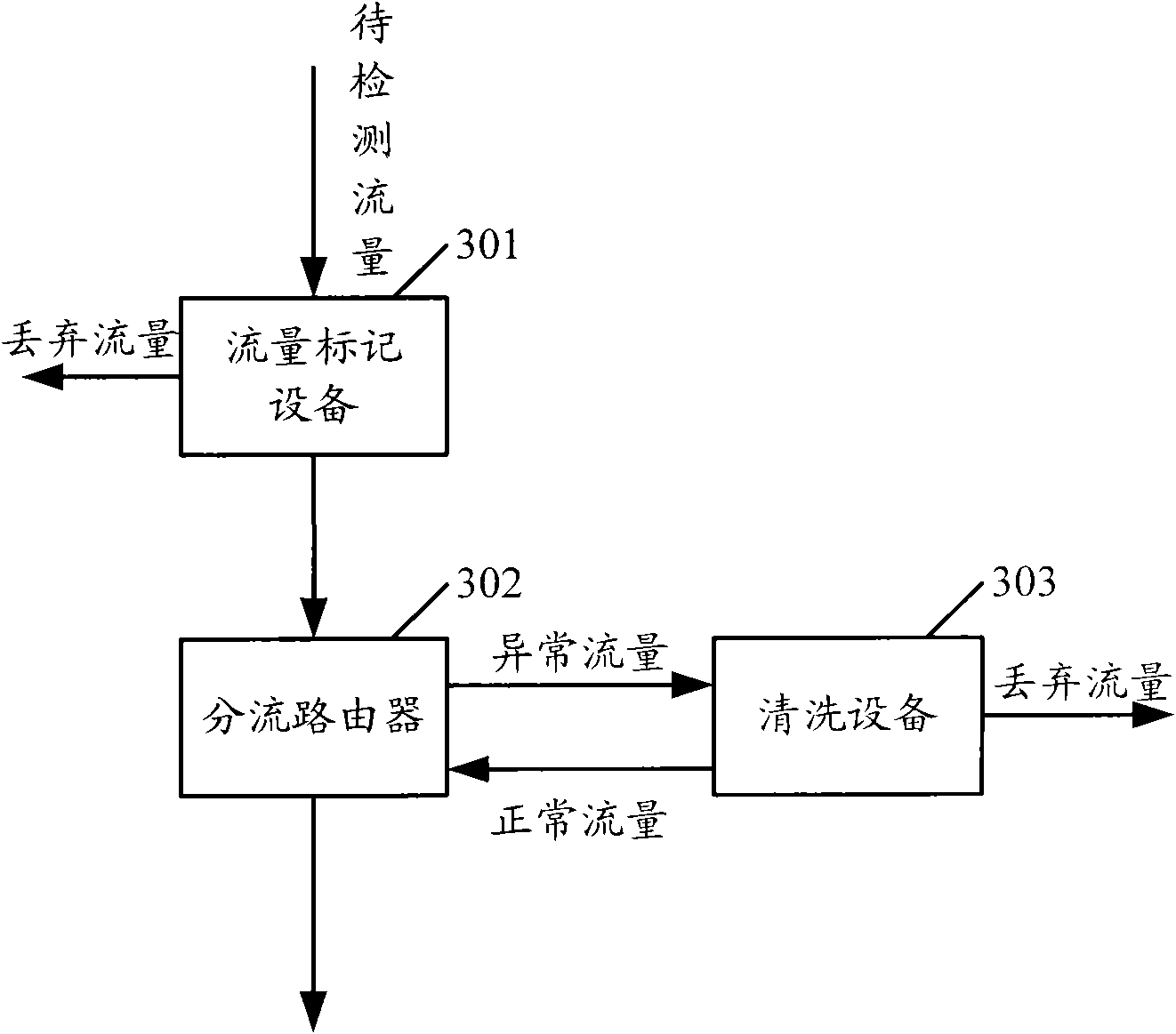
[0030] image 3 It is a structural diagram of the first flow control system provided by the present invention.
[0031] Such as image 3 As shown, the first traffic control system provided by the present invention includes a traffic marking device 301 , a distribution router 302 and a cleaning device 303 .
[0032] The traffic marking device 301 identifies abnormal traffic from current traffic, and identifies the abnormal traffic.
[0033] The distribution router 302 routes the identified abnormal traffic to the cleaning device 303 .
[0034] The cleaning device 303 cleans the abnormal flow.
[0035] Usually, after cleaning the abnormal traffic, the cleaning device 303 deletes the traffic mark contained in the cleaned traffic, and then returns it to...
PUM
 Abstract
Description
Claims
Application Information