
Hot backup matrix of NGB (Next Generation Broadcasting) optical network
A technology of hot backup and optical network, applied in the field of optical network transmission, to achieve the effect of reducing costs, reducing optical transmitters, and improving reliability
- Summary
- Abstract
- Description
- Claims
- Application Information
AI Technical Summary
Problems solved by technology
Method used
Image

Examples
Embodiment Construction
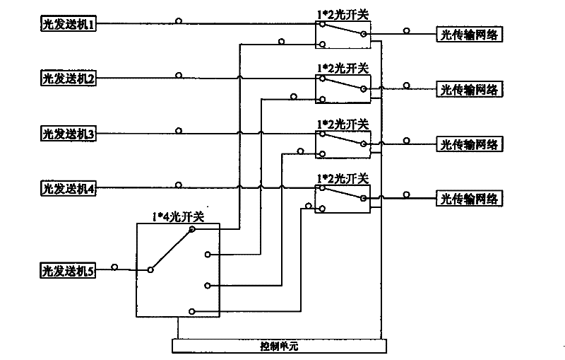
[0018] See image 3 In the illustrated embodiment, a NGB optical network hot backup matrix is mainly composed of an optical transmitter, an optical switch, and a control unit. Multiple groups of optical transmitters are respectively connected to multiple groups of 1*2 optical switches through optical fibers, and the optical switches are connected to optical switches through optical fibers. For the transmission network, add an optical transmitter to connect to 1*4 optical switches. The optical switches are respectively connected to multiple groups of 1*2 optical switches, and a control unit is installed. The control unit controls and connects multiple groups of 1*2 optical switches and 1* 4 optical switches, 1*4 optical switches and multiple sets of 1*2 optical switches form an optical switch matrix.
[0019] See image 3 , Figure 4 In the illustrated embodiment, when all the optical transmitters are in normal condition, the 1*4 optical switches in the optical matrix are i...
PUM
 Abstract
Description
Claims
Application Information