Semi-automatic tin dipping machine

A tin dipping machine and semi-automatic technology, applied in tin feeding devices, metal processing equipment, manufacturing tools, etc., can solve the problems of unstable finished product size, difficult to guarantee the appearance quality, inconsistent tin dipping length of braided bell mouth, etc., and achieve the improvement effect , fast speed and good size consistency

Inactive Publication Date: 2011-11-30
雷特威连接系统(苏州工业园区)有限公司
View PDF8 Cites 23 Cited by
  • Summary
  • Abstract
  • Description
  • Claims
  • Application Information

AI Technical Summary

Problems solved by technology

[0003] In order to solve the problem that the appearance quality of wire rods is difficult to guarantee by manual tinning in the prior art, there are often problems of braided bell mouth, bulging, inconsistent length of dipping tin, and unstable finished product size.

Method used


Image

  • Semi-automatic tin dipping machine
  • Semi-automatic tin dipping machine
  • Semi-automatic tin dipping machine

Examples


Embodiment Construction

[0024] The present invention will be further described below in conjunction with the accompanying drawings.

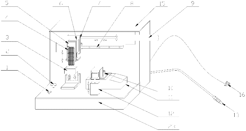
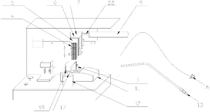
[0025] Such as Figure 2-3 As shown, a semi-automatic tin dipping machine includes start switch 1, emergency stop switch 2, flux tank 2, wiring board 4, positioning plate 5, cylinder two 6, cylinder fixing block 7, guide rail 8, cylinder three 9, dipping Tin bath 10, tin melting furnace 11, cylinder one 12, compressed air connector 13, electrical cabinet 15 and workbench 23. A tin melting furnace 11 is arranged on the workbench 23, and an electrical cabinet 15 is arranged at the rear of the workbench 23, and the electrical cabinet 15 is connected with the power plug 16 through electric wires. A compressed air connector 13 is arranged on the outside of the workbench 23. One end of the compressed air connector 13 is connected to the electrical cabinet 15, and the other end is connected to the air compressor. The electrical cabinet 15 is respectively connected to cylinde...


PUM


Abstract

The invention discloses a semi-automatic wicking machine comprising a workbench, a fixing plate and a tin melting furnace. The semi-automatic wicking machine is characterized by further comprising a wicking groove, a soldering flux groove, a wiring plate, a guide rail, a first up-and-down moving device, a horizontal driving device and a second up-and-down moving device. The wicking groove is arranged above an opening of the tin melting furnace, the first up-and-down moving device is connected with the wicking groove, the soldering flux groove is arranged above the workbench, the second up-and-down moving device is connected with the wiring plate, the back end of the second up-and-down moving device is connected with the guide rail arranged on the fixing plate, and the horizontal driving device arranged on the fixing plate is connected with the second up-and-down moving device. The invention solves the problem that woven flare opening and bulging usually generate, the wicking length isinconsistent, and the sizes of finished produces are unstable due to the hard guarantee of the appearance and the quality of products because wire rods are wicked manually in prior art, and provides a semi-automatic wicking machine with unity in wicking, order appearance and good size consistency.

Description

technical field [0001] The invention relates to a tinning device for cables, in particular to a semi-automatic tinning machine for braiding tinning on micro-coaxial cables in the electronic industry. Background technique [0002] Such as figure 1 As shown, the structure of the electric wires and cables used on the electronic equipment from the outside to the inside is the outer jacket 31, the braided layer 32, the insulating layer 33 and the core wire 34, in order to make the braided layer 32 and the core wire 34 not Loose, which is convenient to ensure the welding quality of the subsequent process and meet certain high-frequency performance. It is often used to dip tin at one end of the wire or cable, and the requirement for the size of the dipped tin is relatively high. At present, it is generally adopted to manually put the braided layer 32 and the core wire 34 of the wire directly into a tin melting furnace at a high temperature of about 250 degrees for a period of time...

Claims


Application Information

Patent Timeline
Patent Type & Authority Applications(China)
IPC IPC(8): B23K3/06
Inventor 毛勇
Owner 雷特威连接系统(苏州工业园区)有限公司
Why Eureka
Try Eureka