Galloping positioning system and positioning method of transmission conductors based on micro-inertial measurement combination

A technology of micro-inertial measurement and power transmission wire, which is used in measurement devices, vibration testing, and testing of machine/structural components. data, etc.

Active Publication Date: 2011-12-14
西安金源电气股份有限公司
View PDF4 Cites 53 Cited by
  • Summary
  • Abstract
  • Description
  • Claims
  • Application Information

AI Technical Summary

Problems solved by technology

[0004] The purpose of the present invention is to provide a galloping positioning system for transmission wires based on micro-inertial measurement, which solves the problem that the existing wire galloping monitoring system can only achieve qualitative analysis of the line and cannot provide scientific data for galloping mechanism analysis and design of anti-galling devices and basic information, and their work is greatly affected by the environment

Method used


Image

  • Galloping positioning system and positioning method of transmission conductors based on micro-inertial measurement combination
  • Galloping positioning system and positioning method of transmission conductors based on micro-inertial measurement combination
  • Galloping positioning system and positioning method of transmission conductors based on micro-inertial measurement combination

Examples


Embodiment Construction

[0066] The present invention will be described in detail below in conjunction with the accompanying drawings and specific embodiments.

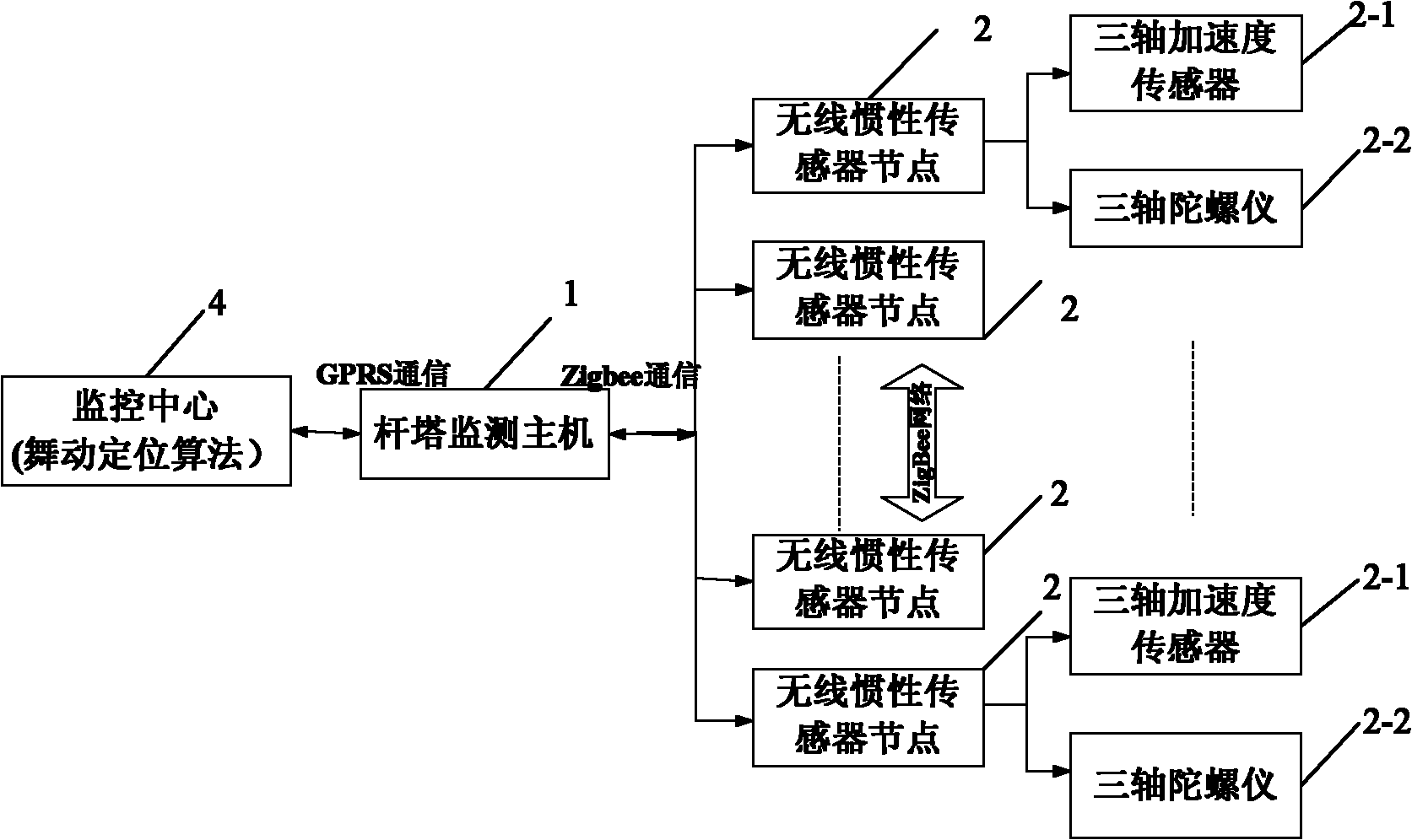
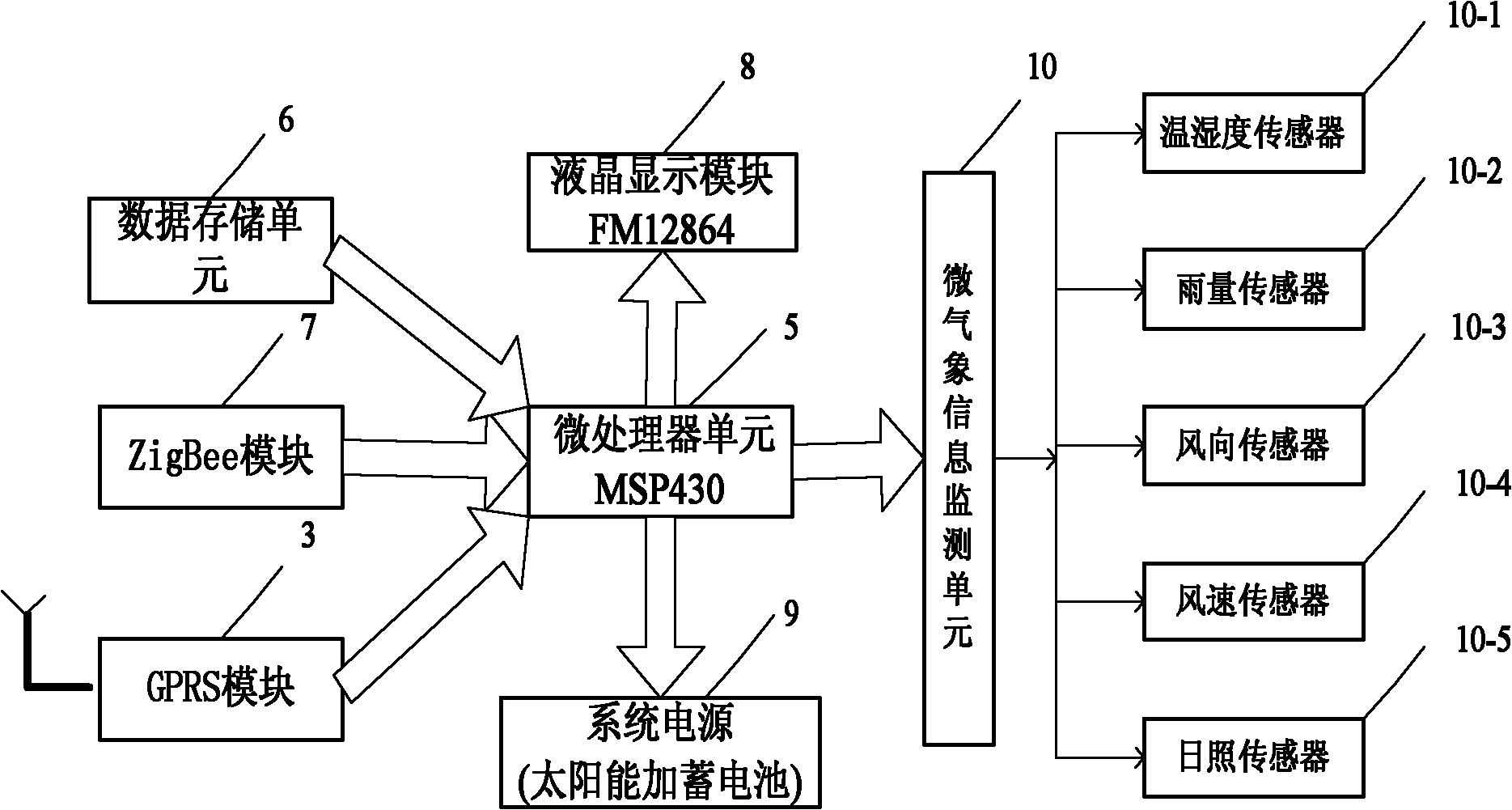
[0067] The present invention is based on the structure of the transmission conductor galloping positioning system based on micro-inertial measurement, such as figure 1 As shown, the connected tower monitoring host 1 and the monitoring center 4 are included. There are multiple wireless inertial sensor nodes 2 through wireless connection on the tower monitoring host 1. Each wireless inertial sensor node 2 includes a triaxial acceleration sensor 2-1 and a three-axis acceleration sensor 2-1. axis gyroscope 2-2. The structure of tower monitoring host 1 is as follows: figure 2 Shown, comprise microprocessor unit 5, be respectively connected with data storage unit 6, ZigBee module 7, GPRS module 3, liquid crystal display module 8, system power supply 9 and micro weather information monitoring unit 10 on the microprocessor unit 5; The information ...


PUM


Abstract

The invention discloses a transmission line oscillation positioning system based on micro inertial measurement combination. The transmission line oscillation positioning system comprises a monitoring center and a pole and tower monitoring host machine which are connected with each other, wherein the pole and tower monitoring host machine is wirelessly connected with at least two wireless inertialsensor nodes; and each wireless inertial sensor node comprises a triaxial acceleration sensor and a triaxial gyroscope. By the method for positioning by adopting the system, the wireless inertial sensor nodes acquire acceleration values and state space angles of a lead wire monitoring point in three directions; the monitoring center processes and analyzes the data of each monitoring point by adopting algorithms, such as Fourier transformation, a least square method, digital filtering, Kalman filtering, matrix coordinate transformation, frequency domain integral operation so as to fit to acquire an oscillation trace of a whole line, and corrects the oscillation line according to a digital model of a relation between an oscillation characteristic value and a micro meteorological condition; therefore, the precision of oscillation monitoring is improved and the most direct and intuitive monitoring of transmission line oscillation can be realized.

Description

technical field [0001] The invention belongs to the technical field of on-line monitoring of the state of power transmission and transformation equipment, and relates to a galloping positioning system for power transmission wires, in particular to a galloping positioning system for power transmission wires based on micro-inertial measurement, and also relates to a positioning method for the above system. Background technique [0002] In recent years, with the rapid development of UHV transmission projects in my country, the frequency and intensity of galloping accidents on overhead transmission lines have increased significantly, and galloping has become one of the most important factors threatening line safety in my country. my country is one of the areas where conductor galloping frequently occurs in the world, and galloping involves transmission lines of various voltage levels. Since 2000, serious galloping accidents have occurred in our country almost every year, serious...

Claims


Application Information

Patent Timeline
Patent Type & Authority Applications(China)
IPC IPC(8): G01M7/02
Inventor 黄新波李国倡赵隆
Owner 西安金源电气股份有限公司
Why Eureka
Try Eureka