Vehicle rear confirmation device

A technology for confirming devices and vehicles, which can be used in vehicle cleaning, vehicle maintenance, vehicle parts, etc., to solve problems such as reduced appearance, and achieve the effect of high degree of freedom of setting and improved appearance quality.

Active Publication Date: 2011-12-21
HONDA MOTOR CO LTD
View PDF8 Cites 2 Cited by
  • Summary
  • Abstract
  • Description
  • Claims
  • Application Information

AI Technical Summary

Problems solved by technology

[0005] However, the above-mentioned conventional rear checking device mainly can accurately grasp the positional relationship in the vehicle width direction by making the mark on the reflector coincide with the mark on the rear part of the vehicle body on the mirror surface. Requirements for the proximity of the rear end of the
[0006] As its countermeasure, the following method is also considered. Marking a mark displ

Method used


Image

  • Vehicle rear confirmation device
  • Vehicle rear confirmation device
  • Vehicle rear confirmation device

Examples


Embodiment Construction

[0052] Embodiments of the present invention will be described below with reference to the drawings. In addition, in each embodiment described below, the same code|symbol is attached|subjected to the same part, and overlapping description is abbreviate|omitted.

[0053] first of all, yes Figure 1 to Figure 5 The first embodiment shown will be described.

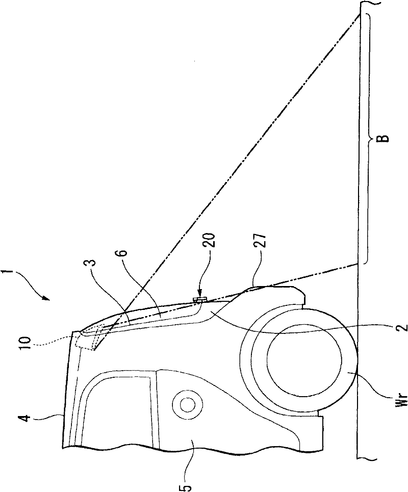
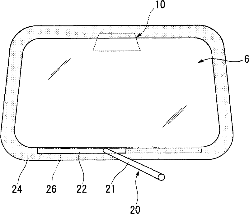
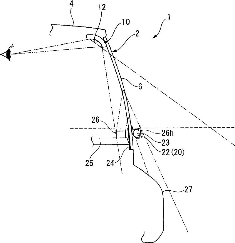
[0054] figure 1 It is a figure showing the side surface of the rear part side of the one box type (one box type) vehicle 1 which has a hatchback type back door 2 (tailgate). In the figure, 3 denotes a rear window provided on the upper portion of the back door 2, 4 denotes a roof panel of the vehicle, 5 denotes a rear side door, and Wr denotes a rear wheel. In addition, in this figure, 6 is a rear windshield attached to the rear window 3, 20 is a rear wiper for wiping the rear surface of the rear windshield 6, and 10 is a screen for mapping the vehicle 1 to the occupants in the vehicle interior. lower rear ( figure 1 The ...


PUM


Abstract

A vehicle rear viewing device includes a rear under view mirror (10)provided to face an inner surface of a rear windshield (6)and capable of reflecting an area below and behind a vehicle to an occupant in an interior of the vehicle. A marker indicator (26) is to allow the occupant to view the area below and behind the vehicle through the rear under view mirror (10)to visually recognize a position of a rear end of a vehicle body. A rear wiper (20) is provided on a rear part of the vehicle body so as to face an outer surface of the rear windshield. The marker indicator is provided so as to be covered with at least a part of the rear wiper along a front rear direction of the vehicle in front of the rear wiper when the rear wiper is in an initial position.

Description

technical field [0001] The present invention relates to a rearward confirmation device for mapping a vehicle under a rear portion of a vehicle body using a rear-view mirror. Background technique [0002] As a vehicle rear checking device, there is known a rear-view mirror that uses a rear-view mirror that maps a lower rear portion of a vehicle body to an occupant in a driver's seat (for example, refer to Patent Document 1). [0003] The rear confirmation device described in Patent Document 1 is designed such that the rear-view mirror is arranged on the front surface side (vehicle interior side) or the rear surface side (vehicle exterior side) of the rear windshield, and the reflector of the rear-view mirror Marks such as lines or triangles are provided for alignment with the rear of the vehicle body mapped on the mirror, and the driver who visually recognizes the rear can accurately align the marks on the mirror with the marks on the rear of the vehicle body on the mirror su...

Claims


Application Information

Patent Timeline
IPC IPC(8): B60R1/04B60S1/04
CPCB60R1/08B60R1/04G02B27/0189G02B27/01
Inventor 植松博岸本雄也桥本敏宏桑岛悠司佐佐木未来藤原知幸
Owner HONDA MOTOR CO LTD
Why Eureka
Try Eureka