Insulation driving circuit of power switching tube

A technology for isolating the drive circuit and the power switch tube, which is applied to the output power conversion device, electrical components, etc., can solve the problems of the slow turn-off process and the easy failure of the power switch tube.

Inactive Publication Date: 2012-01-04
SHENZHEN ACAD OF AEROSPACE TECH
View PDF5 Cites 23 Cited by
  • Summary
  • Abstract
  • Description
  • Claims
  • Application Information

AI Technical Summary

Problems solved by technology

[0007] The purpose of the embodiments of the present invention is to provide an isolated drive circuit for a power switch tube, which aims to solve the problems in the prior art that the power switch tube has a slow turn-off process and is prone to failure.

Method used


Image

  • Insulation driving circuit of power switching tube
  • Insulation driving circuit of power switching tube
  • Insulation driving circuit of power switching tube

Examples


Embodiment Construction

[0025] In order to make the object, technical solution and advantages of the present invention clearer, the present invention will be further described in detail below in conjunction with the accompanying drawings and embodiments. It should be understood that the specific embodiments described here are only used to explain the present invention, not to limit the present invention.

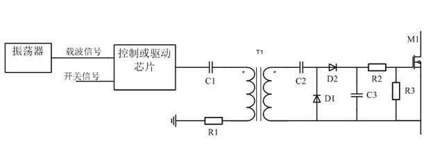
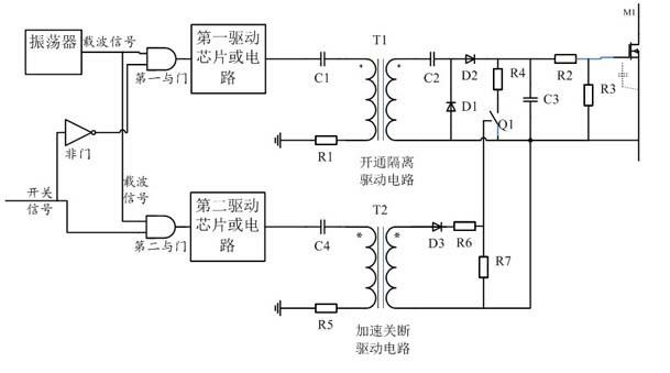
[0026] see Figure 2-3 , shows the isolated drive circuit of the power switch tube provided by the embodiment of the present invention, and the external control circuit outputs the switch signal for controlling the power switch tube M1 to be turned on or off to the input terminal of the isolated drive circuit.

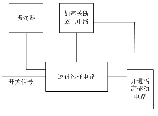
[0027] The isolation drive circuit of the power switch tube includes an oscillator for generating a carrier signal, and a logic selection circuit connected to the oscillator, and the logic selection circuit is also respectively connected to an accelerated turn-off discharge circuit and a tu...


PUM


Abstract

The invention is suitable to the field of electrical switches and switch power-supplies, and provides an insulation driving circuit of a power switch tube. According to the invention, on the basis of the insulation driving circuit of the traditional power switch tube, the reliability and stability of the insulation driving circuit in conduction and disconnection are improved through increasing the gate filter capacitance of the power switch tube and correspondingly accelerating disconnection of a discharge path; the acceleration for the disconnection of the discharge path works when the gate filter capacitance is greater, the gate filter capacitance is subjected to rapid discharge when in disconnection, and the switch oscillation phenomenon of MOSFET (metal-oxide-semiconductor field effect transistor) caused by slow decrease of a gate voltage is avoided; when the gate filter capacitance is greater, the gate voltage is very stable, which is very good for the MOSFET; and when an input signal is at a close state, through accelerating the disconnection of the discharge path, a gate of the MOSEFT is discharged all along, thus the gate voltage cannot be accumulated, and the error conduction of the power switch tube which is required to be turned off is avoided.

Description

technical field [0001] The invention belongs to the field of electrical switches and switching power supplies, in particular to an isolated drive circuit for a power switch tube, in particular to an isolated drive circuit with an accelerated turn-off path. Background technique [0002] For the occasion where the power switch tube is used for circuit switching, it is necessary to isolate the drive from the control circuit from the power switch tube due to application requirements or for circuit safety considerations. On the premise of ensuring long-term reliable turn-on and turn-off, the driving circuit needs to have a certain switching rate. [0003] The isolated driving circuit structure of the power switch tube in the prior art that is turned on and off for a long time is as follows: figure 1 As shown, including: oscillator, driver chip or circuit, primary side DC blocking capacitor C1, primary side current limiting resistor R1, drive transformer T1, secondary side DC blo...

Claims


Application Information

Patent Timeline
Patent Type & Authority Applications(China)
IPC IPC(8): H02M1/08
Inventor 付明王骞
Owner SHENZHEN ACAD OF AEROSPACE TECH
Why Eureka
Try Eureka