

Drive device for wind turbine
A technology for transmissions and wind turbines, applied in transmissions, mechanical power transmission, wind engines, etc., to reduce the number of components, reduce maintenance requirements, and reduce corrosion
- Summary
- Abstract
- Description
- Claims
- Application Information
AI Technical Summary
Problems solved by technology
Method used
Image

Examples
Embodiment Construction
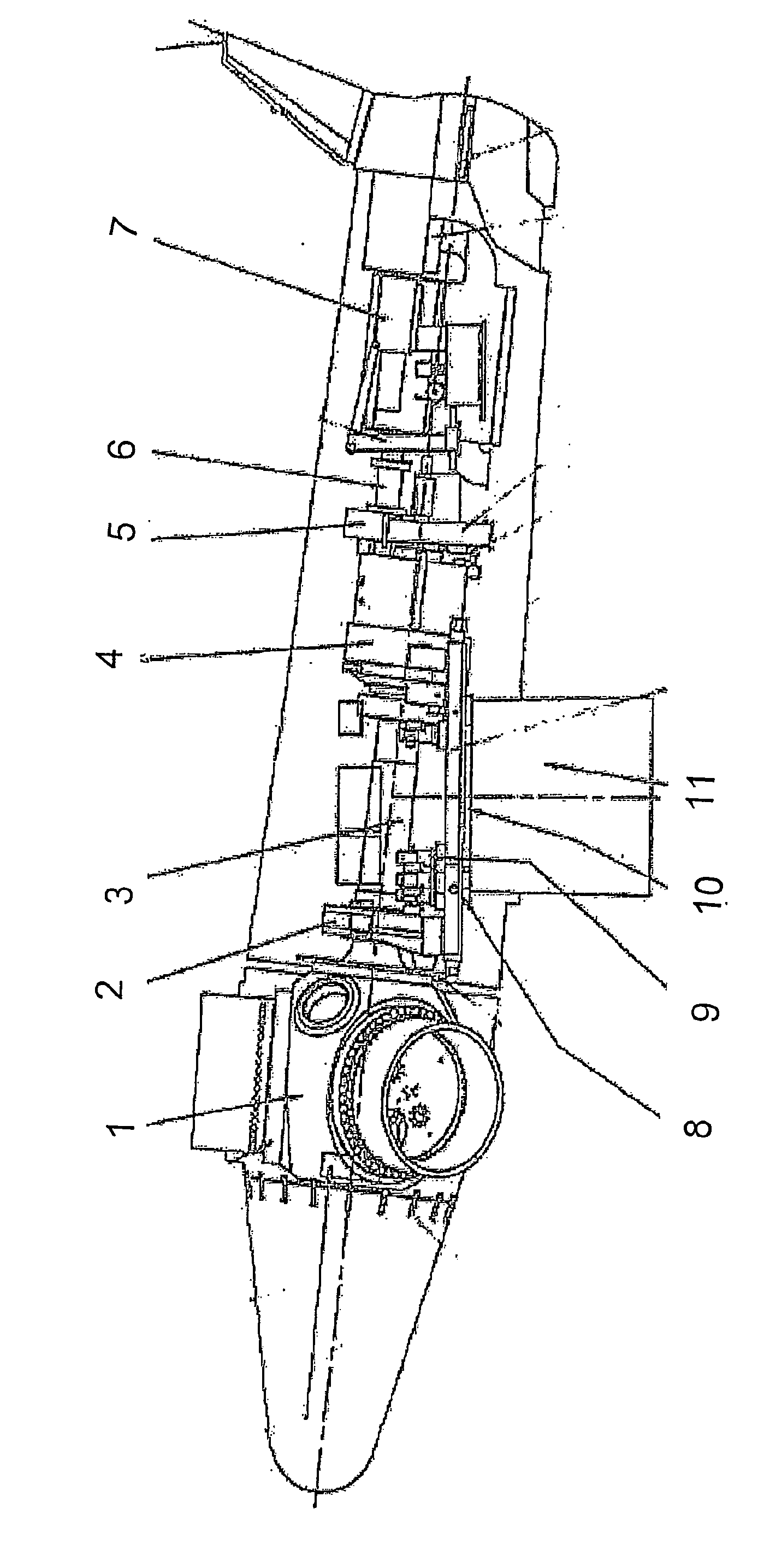
[0029] First, a brief introduction based on figure 1 known cabins. It comprises a rotor hub 1 to which a wind turbine blade (not shown) is attached. Hub 1 is mounted in main bearing 2 and connected to main shaft 3 . The main shaft is connected to main gear 4. The gear 4 is equipped with a brake 5 . The gear is connected to a generator 7 via a connection 6 . The nacelle is also equipped with a swivel bearing 8 , a swivel gear 9 and a swivel ring 10 in order to rotate the nacelle with respect to the tower 11 on which the nacelle is placed.
[0030] The purpose of the invention is to replace the following components in the known nacelle described above: the main shaft 3 , the main gear 4 , the brake 5 and the connection 6 .
[0031] figure 2 show figure 1 The nacelle in has the transmission according to the invention placed in the desired position and with the known nacelle as background.
[0032] However, in the introduction figure 2 Before, you should refer to Figu...
PUM
 Abstract
Description
Claims
Application Information