Dialysis machine, manifold for the dialysis machine and process

A technology of dialysis machine and manifold, applied in the field of dialysis machine

Active Publication Date: 2012-02-01
VIFOR INT AG
View PDF10 Cites 4 Cited by
  • Summary
  • Abstract
  • Description
  • Claims
  • Application Information

AI Technical Summary

Problems solved by technology

Dosing all medications to all patients each day without errors is difficult due to time pressure

Method used


Image

  • Dialysis machine, manifold for the dialysis machine and process
  • Dialysis machine, manifold for the dialysis machine and process
  • Dialysis machine, manifold for the dialysis machine and process

Examples


Embodiment Construction

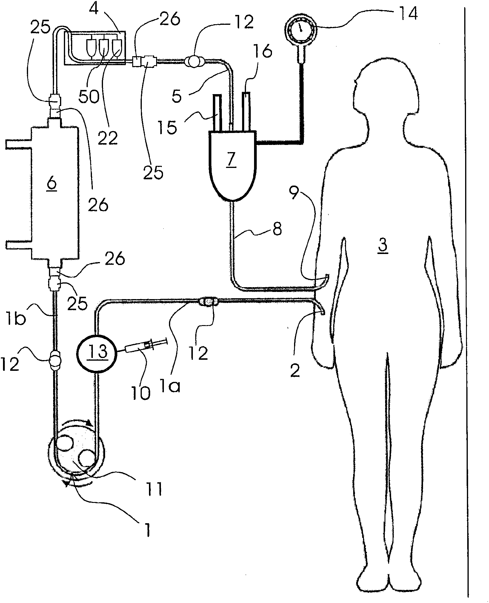
[0055] figure 1 The dialysis machine comprises a first plastic tube 1 which is connected on one side to the AV fistula 2 of the patient 3 and on the other side to the inlet of the dialyzer 6 . The second plastic tube 5 is connected on one side with the outlet of the manifold 4 and on the other side with the inlet on top of the air collector 7 . A third plastic tube 8 is connected on one side to the outlet at the bottom of the air collector 7 and on the other side to the inlet of a vein 9 into the patient's 3 forearm. The inlet of the manifold 4 is connected with the outlet at the top of the dialyzer 6 . It is also possible to arrange a manifold between the inlet of the dialyzer and the tube 1 . However, in such a case it is not possible to insert a container containing a drug which is not allowed to pass through the dialyzer 6 into the manifold.

[0056]The dialysis machine may comprise a buffer 13 arranged between the AV fistula 2 and the peristaltic pump 11 . To prevent ...


PUM


Abstract

The present invention relates to a dialysis machine for the purification of blood, a manifold for the dialysis machine as well as to a process for the regeneration of the dialysis bath. It is an object of the present invention to provide a dialysis machine, a manifold for the dialysis machine as well a process which facilitates the administration of medical preparations during a dialysis procedure. In order to solve the object, a dialysis machine according to the present invention comprises tubes (1, 5, 8) connected with a dialyzer (6), means for delivering pharmaceuticals into the tubes and a pump (11) for the transport of blood through the tubes and the dialyzer. The dialysis machine comprises means for administration (4) of at least one pharmaceutical by a suction effect of the pump or by a pressure effect of the pump or by an excess pressure of a gas or a liquid.

Description

technical field [0001] The invention relates to a dialysis machine for purifying blood, a manifold for the dialysis machine and a method for regeneration of dialysate. Background technique [0002] Dialysis works on the principles of dispersion of solutes and ultrafiltration of fluids through semipermeable membranes. Blood flows through one side of the semipermeable membrane, while dialysate, or fluid, flows through the opposite side. Smaller solutes and fluids pass through the diaphragm. Blood flows in one direction and dialysate flows in the opposite direction. The countercurrent flow of blood and dialysate maximizes the solute concentration gradient between blood and dialysate, which helps remove more urea and creatinine from the blood. Solute (such as potassium, phosphorus, and urea) concentrations are undesirably high in the blood and low or absent in the dialysate, and frequent replacement of the dialysate ensures that unwanted solute concentrations are kept relativ...

Claims


Application Information

Patent Timeline
Patent Type & Authority Applications(China)
IPC IPC(8): A61M1/36A61M5/14A61M39/04
CPCA61M2001/3437A61M1/3672A61M1/3675A61M5/16881A61M2001/3458A61M39/10A61M2001/3431A61M5/1408A61M1/3437A61M1/3458A61M1/3434A61M1/14A61M1/3431
Inventor L·D·韦贝尔
Owner VIFOR INT AG
Why Eureka
Try Eureka