
Safety device for anastomat
A safety device and a stapler technology, applied in the direction of surgical fixation nails, etc., can solve the problems of easy forgetting to open, unusable instruments, affecting the operation process, etc.
- Summary
- Abstract
- Description
- Claims
- Application Information
AI Technical Summary
Problems solved by technology
Method used
Image

Examples
Embodiment Construction
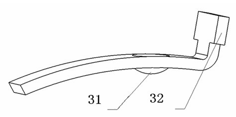
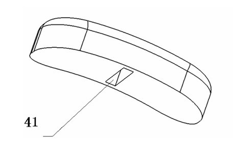
[0021] A stapler safety device of the present invention comprises a fixed handle 1, a movable handle 2, a safety piece 3, a safety push twist 4 and a supporting handle 5, the safety piece 3 and the safety push twist 4 are fixedly connected, and are slidably installed on the support handle 5, the other end of the support handle 5 is fixed on the fixed handle 1, and the end of the docking of the movable handle 2 and the support handle 5 is provided with a snap-in slot 21 that can be inserted into the safety piece 3.
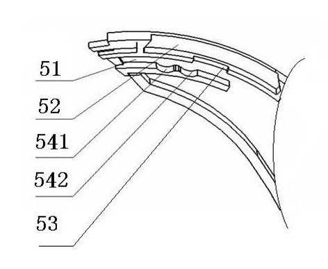
[0022] refer to figure 1 , figure 2 As shown, wherein the support handle 5 is provided with a safety plate sliding guide rail 51, and a chute 52 for installing the safety push button 4, and a through groove 53 is also provided in the chute 52 to cooperate with the installation of the safety plate 3, and the safety plate sliding guide rail 51 Grooves are also arranged on the bottom surface, and the sliding guide rail 51 of the safety piece and the sliding groove 5...
PUM
 Abstract
Description
Claims
Application Information