Concrete moulding bed structure and pouring method

A technology of concrete and pouring concrete, which is applied in basic structure engineering, excavation, construction, etc., can solve problems such as waste of manpower and material resources, environmental hazards, and delay in construction time, so as to save formwork and labor, save labor and machinery, and save manpower and material resources Effect

Active Publication Date: 2015-04-01
薛忠群
View PDF3 Cites 3 Cited by
  • Summary
  • Abstract
  • Description
  • Claims
  • Application Information

AI Technical Summary

Problems solved by technology

However, the processing method of the brick tire mold itself also has some disadvantages
[0003] Brick tire formwork first needs to build bricks in the foundation pit. Since construction workers need to go down the foundation pit to build bricks, a large construction space is required, which requires a larger area to be excavated when excavating the foundation pit. After the construction of these brick tire molds is completed, a large gap will inevitably be formed between the brick tire molds and the outer wall of the foundation pit, thus requiring a large amount of backfill soil, which greatly wastes manpower and material resources, increases the construction procedure, and delays the construction time.
From this point of view, the brick tire mold itself is a processing method with many processes, a large workload, and cannot be formed at one time.
In addition, the brick tire mold requires a large amount of clay bricks, which will cause great harm to the environment

Method used


Image

  • Concrete moulding bed structure and pouring method
  • Concrete moulding bed structure and pouring method
  • Concrete moulding bed structure and pouring method

Examples


Embodiment 1

[0018] Pouring concrete tire mold of the present invention comprises the following steps:

[0019] The first step is to discharge the accumulated water in the foundation pit;

[0020] The second step is to excavate the earthwork to the design depth of the foundation pit;

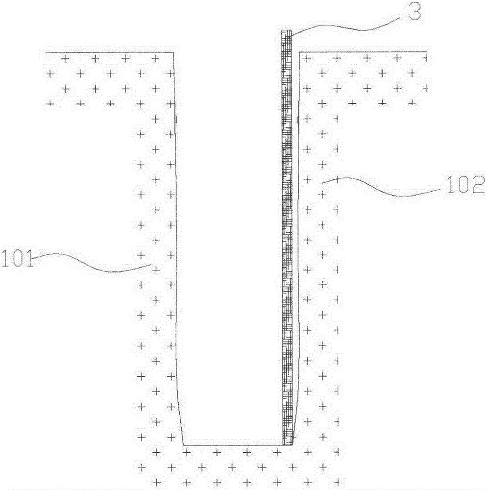
[0021] The third step is as image 3 As shown, the first template 3 is supported along the inner wall of the membrane foundation pit 102;

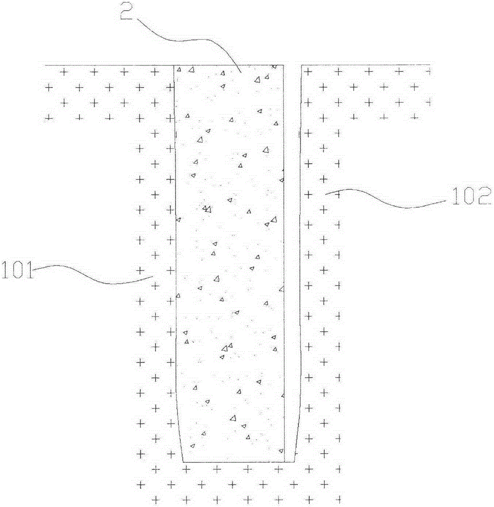
[0022] The fourth step is as Figure 4 As shown, concrete is poured between the outer wall of the foundation pit 101 and the first formwork 3 and compacted by vibrating to complete the pouring of the concrete tire mold 2;

[0023] The fifth step is as Figure 5 As shown, after the strength of the concrete reaches the standard, the template 3 is removed to complete the pouring of the entire concrete tire form.

[0024] From the perspective of this embodiment, when pouring the concrete tire formwork structure described in this embodiment, only a circle of formwork 3 i...

Embodiment 2

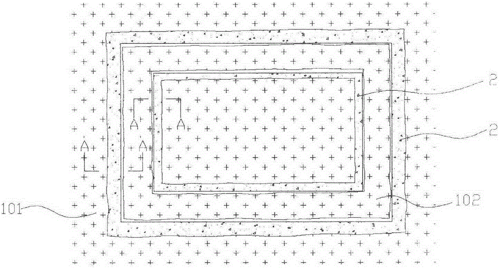
[0026] During the process of pouring the concrete tire form 2, since the outside of the concrete tire form 2 directly uses the excavated foundation pit outer wall 101 as a template, the condition of the foundation pit outer wall 101 affects the pouring of concrete.

[0027] If water seepage enters the foundation pit from the outer wall 101 of the foundation pit, it will definitely affect the strength of the concrete tire mold.

[0028] If the stability of the outer wall 101 of the foundation pit is poor, the soil layer on the outer wall 101 of the foundation pit falls off into the foundation pit, which will affect the smooth progress of concrete pouring. In the process of pouring concrete, once the soil layer of the outer wall 101 of the foundation pit collapses or falls into the concrete, not only will the strength of the concrete be reduced, but also the regularity of the shape of the concrete tire form 2 will be broken, resulting in uneven stress.

[0029] In this embodimen...

Embodiment 3

[0039] Such as Figure 7 , Figure 8 and Figure 9 As shown, the difference with embodiment 2 is that when the fifth step of embodiment 2 is carried out, the steel formwork 5 is not raised after the concrete injection is completed, but the steel formwork 5 is lifted while injecting concrete, and at the same time Vibrate. This embodiment is suitable for deep foundation pits. The deeper the foundation pit, the more concrete needs to be injected. If the steel formwork is lifted after the concrete is poured, it will inevitably be squeezed by the outer wall 101 of the foundation pit and the concrete on the steel formwork 5. Due to the strong friction formed by the pressure, a large mechanical force is needed to lift the steel formwork out of the foundation pit. If just mention steel formwork 5 after concrete pouring is finished, just need to overcome powerful pressure and frictional force, as the power of machinery is less, just can't finish this work. On the contrary, the cons...


PUM


Abstract

The invention discloses a concrete moulding bed structure and a pouring method, belonging to the treatment before pouring of concrete on the foundation in the building construction. The invention aims to solve the problems frequently occurred in the existing common brick moulding bed construction that a great quantity of clay bricks are needed, one-time moulding cannot be realized and a great quantity of backfill is needed after the completion of the construction. The invention provides a structure and pouring method which are time-saving, labor-saving and are beneficial to the environmental protection. The concrete moulding bed structure provided by the invention is composed of a concretemoulding bed, a foundation pit outer wall and a moulding bed foundation pit inner wall, wherein the concrete moulding bed is formed by pouring along the foundation pit outer wall and molded in the longitudinal direction, and the concrete tie shuttering tightly contacts the foundation pit outer wall. The pouring method of the concrete moulding bed structure provided by the invention comprises the steps of performing earth excavation, performing foundation pit dewatering, setting up a concrete moulding bed inner side formwork, pouring the concrete moulding bed, removing the formwork and the like.

Description

technical field [0001] The invention relates to reinforcement of building foundation pits, in particular to foundation tire molds. Background technique [0002] At present, in the process of building construction, brick tire molds are often used. This processing method is simpler and more economical than other methods. However, the processing method of the brick tire mold itself also has some disadvantages. [0003] Brick tire formwork first needs to build bricks in the foundation pit. Since construction workers need to go down the foundation pit to build bricks, a large construction space is required, which requires a larger area to be excavated when excavating the foundation pit. After the construction of these brick tire molds is completed, a large gap will inevitably be formed between the brick tire molds and the outer wall of the foundation pit, thereby requiring a large amount of backfill, which greatly wastes manpower and material resources, increases the constructi...

Claims


Application Information

Patent Timeline
Patent Type & Authority Patents(China)
IPC IPC(8): E02D17/04
Inventor 薛忠群
Owner 薛忠群
Why Eureka
Try Eureka