Material guiding mechanism based on heat radiator

A heat pipe and material guide technology, applied in metal processing, metal processing equipment, manufacturing tools, etc., can solve the problems of low work efficiency, cumbersome installation steps, high labor intensity, etc.

Inactive Publication Date: 2012-09-19
HUANGSHAN KENENG AUTO RADIATOR
View PDF5 Cites 8 Cited by
  • Summary
  • Abstract
  • Description
  • Claims
  • Application Information

AI Technical Summary

Problems solved by technology

[0003] In the assembly process of the existing radiator, due to the uniqueness of its own structure, it still relies on manual operation; when assembling, the inclined working plate is arranged first, and one side splint is placed at the bottom end, and then Place heat pipes and heat dissipation strips in sequence on the slant plate, and rely on the gravity of the above-mentioned components on the slope to realize their preliminary installation; the installation steps are cumbersome, and the staff need to repeatedly pick and place heat dissipation pipes and heat dissipation strips during assembly. The strength is extremely high, especially for the laying of heat pipes and heat dissipation strips. The larger the size of the radiator, the more the number of heat dissipation strips and heat dissipation pipes. Laying in sequence will be more time-consuming and laborious, and the overall work efficiency will be extremely low.

Method used


Image

  • Material guiding mechanism based on heat radiator
  • Material guiding mechanism based on heat radiator
  • Material guiding mechanism based on heat radiator

Examples


Embodiment Construction

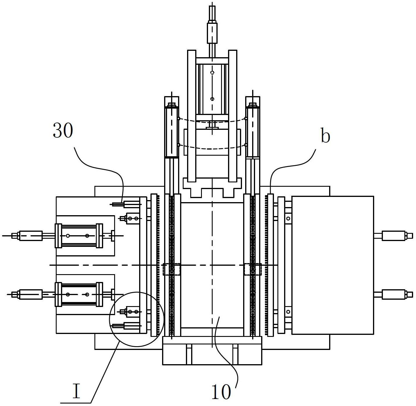
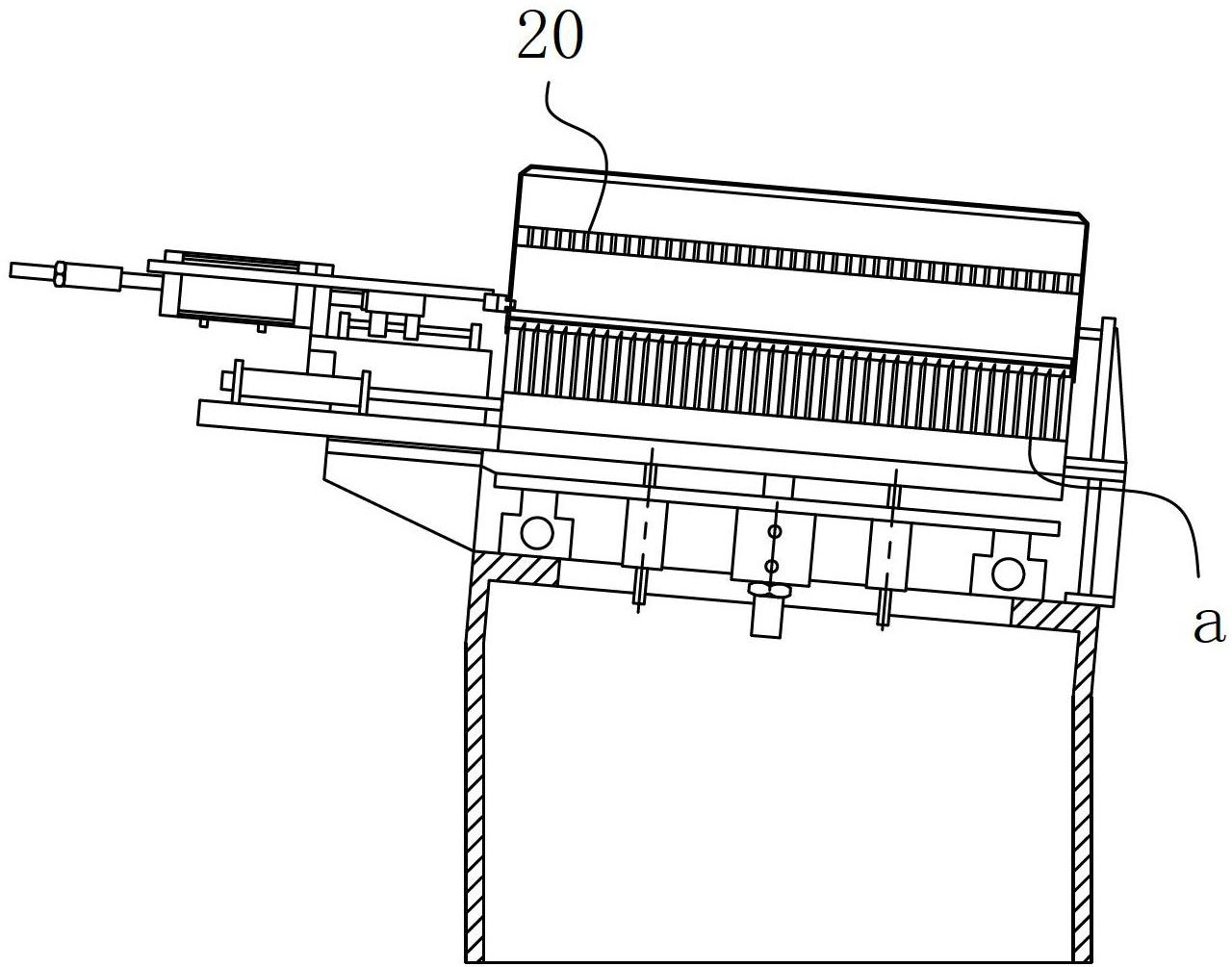
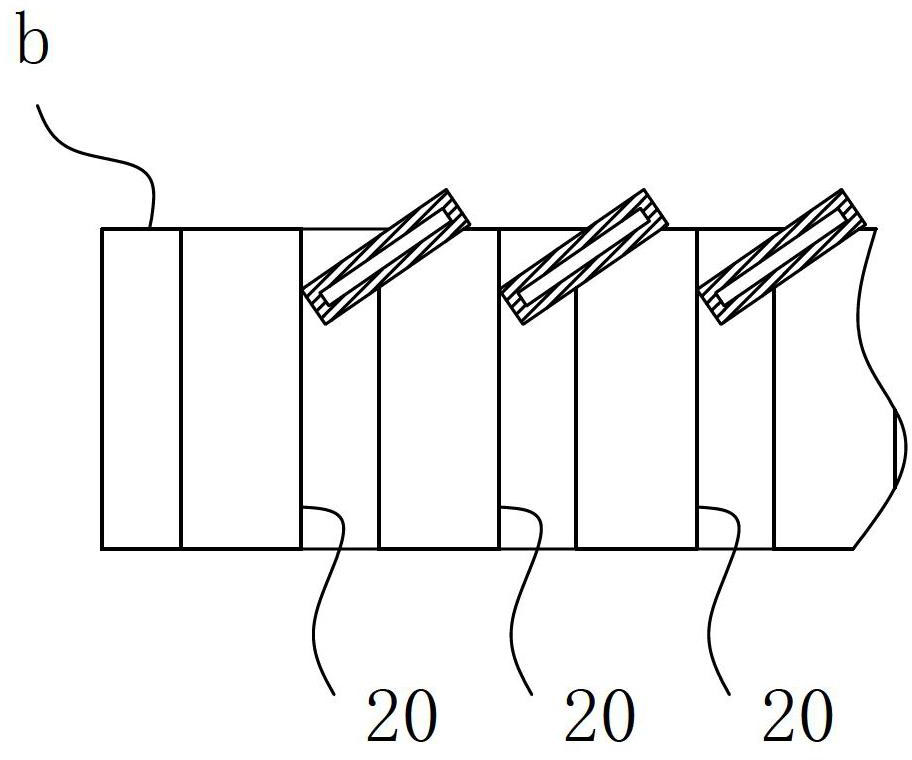
[0011] A material guide mechanism based on heat dissipation pipes, including a work surface 10, a clamping unit arranged on the work surface 10 for receiving and positioning the heat dissipation pipe, and a guide groove 20 located above the clamp unit a, the clamp of the clamp unit a The interface corresponds to the notch of the guide groove 20 and it is correspondingly located on the guide path of the guide groove 20. The arrangement direction of the guide groove 20 is parallel to or intersects with the arrangement direction of the heat dissipation pipes, and the minimum groove width is greater than or equal to the thickness of the heat dissipation pipe. And less than the width of the cooling pipe, the minimum distance between each adjacent guide groove 20 is greater than or equal to the width of the heat dissipation belt in a straight state. The material guide mechanism also includes a power mechanism 30 for driving the guide groove 20 to move. The power mechanism 20 has two ...


PUM


Abstract

The invention belongs to the field of assembly of heat radiators, and particularly relates to a material guiding mechanism based on heat radiating pipes. The material guiding mechanism comprises a working platform surface, a clamping unit and guiding grooves, wherein the clamping unit is arranged on the working platform surface; the guiding grooves are positioned above the clamping unit; clamping ports of the clamping unit correspond to groove ports of the guiding grooves, and are correspondingly positioned on the guiding paths of the guiding grooves; the distributing direction of the guiding grooves is parallel to or intersected with that of heat radiating pipes; the width of the smallest groove is larger than or equal to the thickness of each heat radiating pipe, and is less than the width of each heat radiating pipe; and the shortest distance between all adjacent guiding grooves is larger than or equal to the width of a heat radiating belt in a flat and straight state. The material guiding mechanism also comprises a power mechanism for driving the guiding grooves to move; the power mechanism has two position states, and when the power mechanism is at the initial position, the guiding grooves are positioned above the clamping unit; and when the guiding action is finished, the power mechanism acts and drives the guiding grooves to separate from the positions above the clamping unit. The material guiding mechanism has the advantages that the whole assembling need of the whole heat radiator can be met by one-time pipe distribution, and the working efficiency is high.

Description

technical field [0001] The invention belongs to the field of radiator assembly, and in particular relates to a material guiding mechanism based on a heat dissipation pipe. Background technique [0002] Radiators are an integral part of a car's cooling system. The radiator in the engine water cooling system is usually in the shape of a square frame, consisting of a water inlet chamber, a water outlet chamber, a heat dissipation belt, and a flat tube-shaped heat dissipation pipe. When assembled, the heat dissipation belt and the heat dissipation pipe are arranged alternately one by one. , relying on the splints arranged on both sides to achieve sequential fixation relative to the heat dissipation belt and the two ends of the heat dissipation pipe, and relying on the fixing plates arranged at both ends to realize the clamping and fixing of the heat dissipation belt and the two ends of the heat dissipation pipe, and the outer side of the fixing plate is set with plastic The lay...

Claims


Application Information

Patent Timeline
Patent Type & Authority Applications(China)
IPC IPC(8): B23P19/00
Inventor 方兴武
Owner HUANGSHAN KENENG AUTO RADIATOR
Why Eureka
Try Eureka