

Turbine exhaust device with penetrating pipe
A technology of turbine deflation and penetrating pipes, which is applied in the direction of machines/engines, internal combustion piston engines, mechanical equipment, etc. The structure of the pressure system is complex and other problems, to achieve the effect of power increase, sealing problem solution, and intake flow reduction
- Summary
- Abstract
- Description
- Claims
- Application Information
AI Technical Summary
Problems solved by technology
Method used
Image


Examples
Embodiment
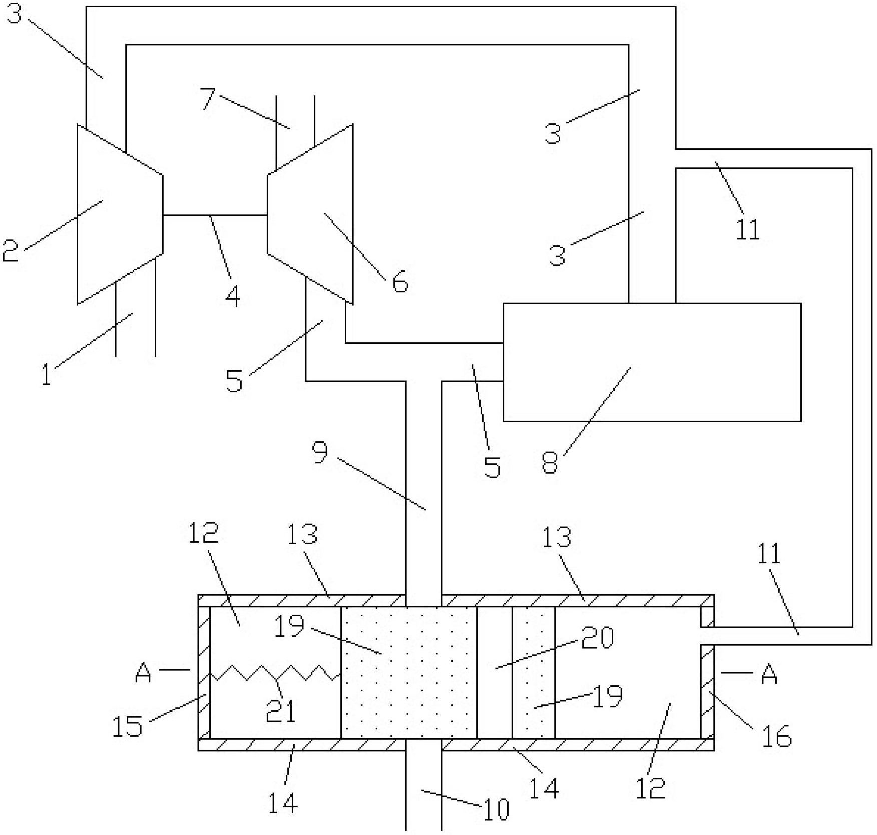
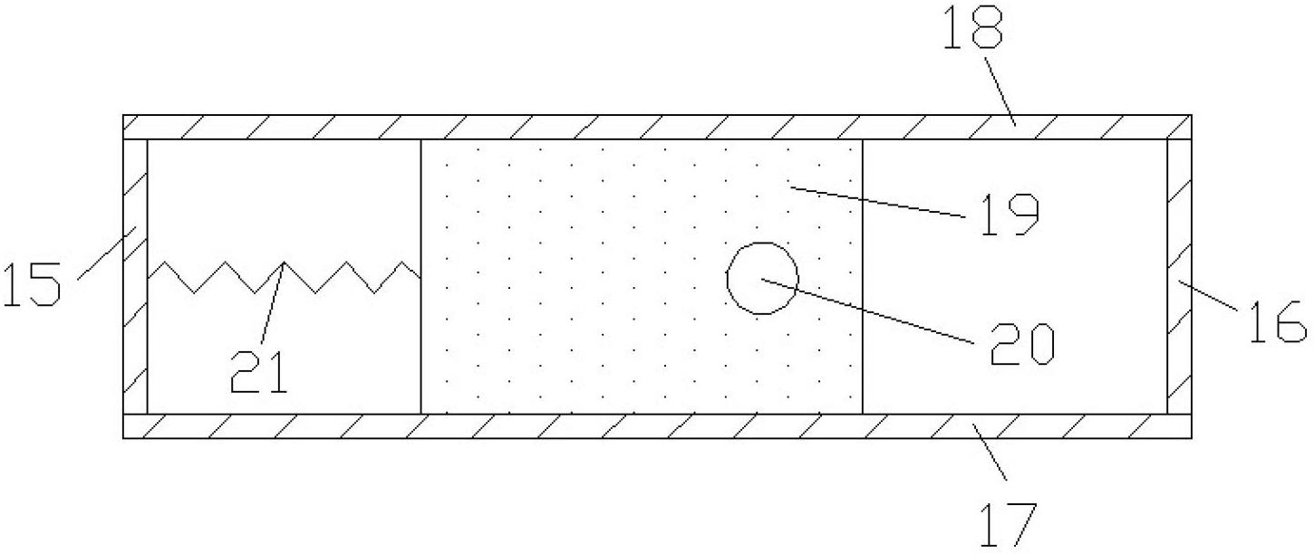
[0014] Such as figure 1 with figure 2 Shown, the present invention comprises: comprise compressor inlet pipe 1, compressor 2, engine inlet pipe 3, connecting shaft 4, engine exhaust pipe 5, turbine 6, turbine outlet pipe 7, engine 8, first connecting pipe 9, Second connecting pipe 10, third connecting pipe 11, volume cavity 12, volume cavity upper wall 13, volume cavity lower wall 14, volume cavity left wall 15, volume cavity right wall 16, volume cavity front wall 17, volume cavity rear wall 18. The moving body 19, the through pipe 20 and the elastic member 21, the compressor 2 and the turbine 6 are connected coaxially through the connecting shaft 4, the air inlet and outlet of the compressor 2 are respectively connected with the air outlet of the compressor inlet pipe 1 and the engine inlet pipe 3 The air inlet is connected, and the air inlet and outlet of the turbine 6 are connected with the air outlet of the engine exhaust pipe 5 and the air inlet of the turbine outlet p...
PUM
 Abstract
Description
Claims
Application Information