

Coiled tubing clamping device and injection head using same
A clamping mechanism and injection head technology, used in drilling pipes, casings, and earth-moving drilling, etc., can solve the problems that the clamping block cannot slide, reduce the service life of the oil pipe, and wear the oil pipe, so as to avoid injury or wear, prolong the The effect of long service life and large follow-up clearance
- Summary
- Abstract
- Description
- Claims
- Application Information
AI Technical Summary
Problems solved by technology
Method used
Image

Examples
Embodiment Construction
[0032] The specific embodiment of the present invention is described in detail below in conjunction with accompanying drawing:
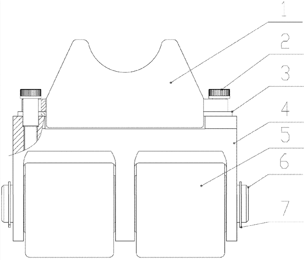
[0033] Such as Figure 1-Figure 7 As shown: a coiled tubing clamping mechanism, including a saddle-shaped clamping block 1 and a clamping block seat 4, the clamping block seat 4 includes a pin shaft 6 and a rolling body 5 sleeved on the pin shaft, the The clamping block seat 4 is provided with two through holes 402 for inserting and connecting the pin shaft with the injection head chain along the direction of the pin shaft 6, and the upper part of the clamping block seat 4 is provided with three partitions 403. The partition 403 is provided with a pin hole 401 for installing the pin 6;
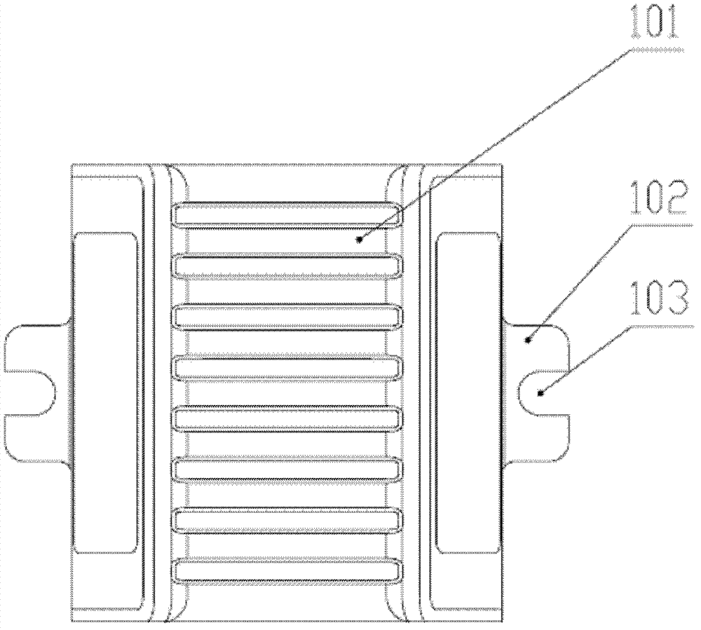
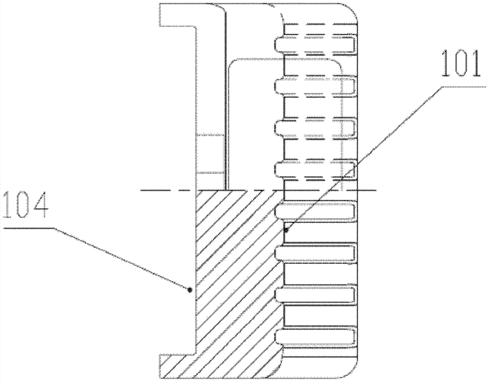
[0034] Both sides of the saddle-shaped clamping block 1 are provided with a tongue table 102, the tongue table 102 is provided with an opening 103, the back of the saddle-shaped clamping block 1 is provided with a groove 104, and the clamping block A pair of bosses...
PUM
 Abstract
Description
Claims
Application Information