Illuminating optical system and projector using same

一种照明光学系统、激光光源的技术,应用在照明光学系统领域,能够解决增加光量等问题,达到高亮度水平、长寿命、小光学扩展量的效果

Inactive Publication Date: 2012-10-17
NEC DISPLAY SOLUTIONS LTD
View PDF1 Cites 6 Cited by
  • Summary
  • Abstract
  • Description
  • Claims
  • Application Information

AI Technical Summary

Problems solved by technology

However, light sources using LEDs are difficult to increase the amount of light without increasing the light emitting area

Method used


Image

  • Illuminating optical system and projector using same
  • Illuminating optical system and projector using same
  • Illuminating optical system and projector using same

Examples


Embodiment Construction

[0026] In the following, exemplary embodiments are described with reference to the accompanying drawings.

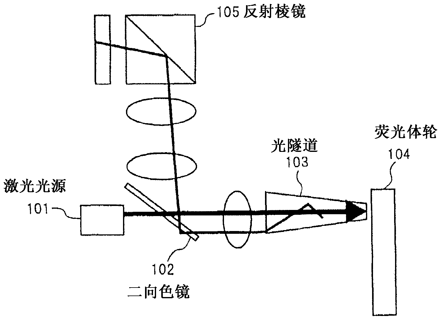
[0027] figure 1 is a block diagram illustrating the configuration of an exemplary embodiment of the illumination optical system according to the present invention.

[0028] This exemplary embodiment includes a laser light source 101 , a dichroic mirror 102 , a light tunnel 103 , a phosphor wheel 104 , and a reflection prism 105 .

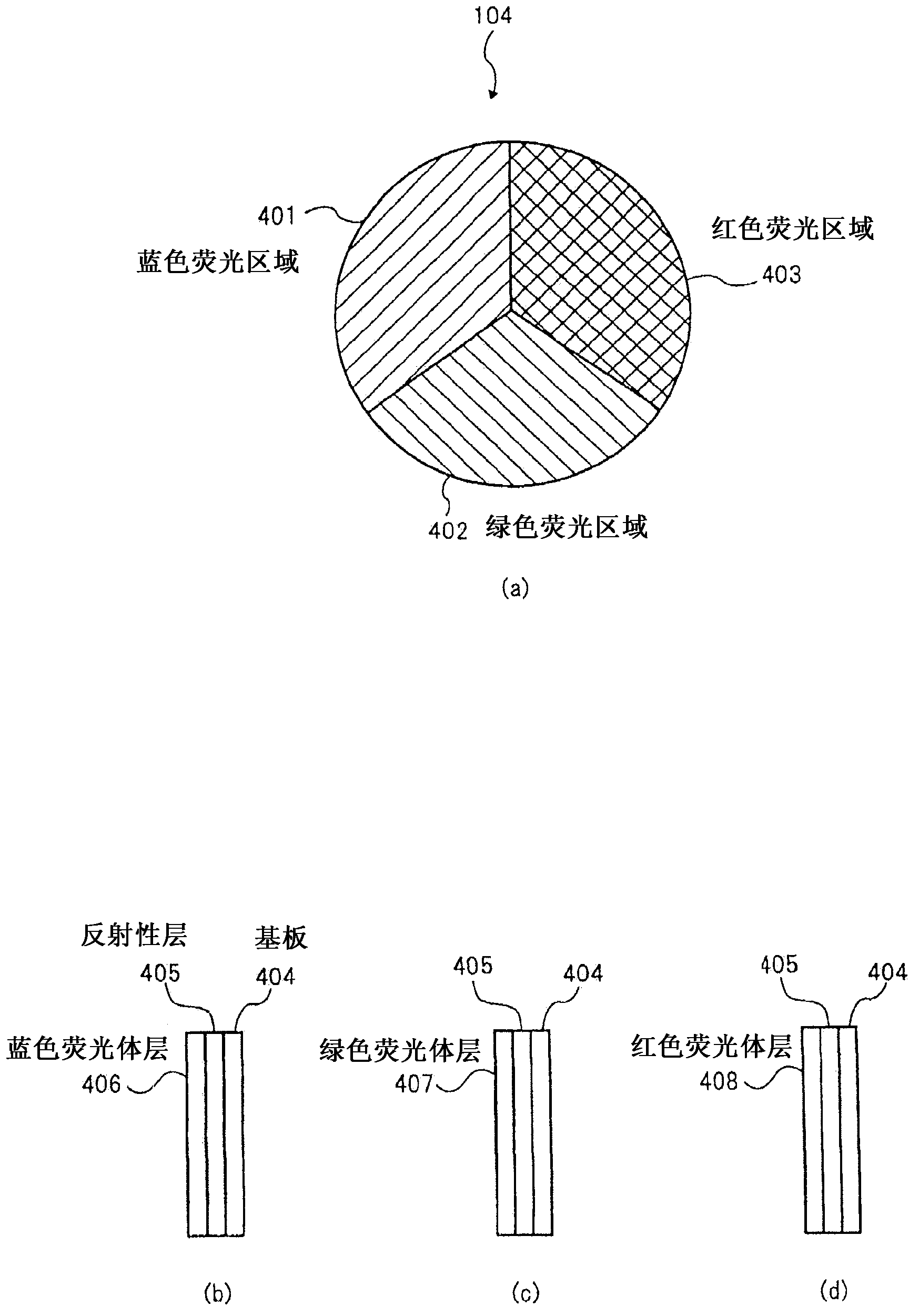
[0029] A laser light source 101 generates laser light that provides excitation light having a wavelength λ1. The laser light generated by the laser light source 101 is incident on the phosphor wheel 104 through the dichroic mirror 102 and the light tunnel 103 . The phosphor wheel 104 includes a plurality of fluorescence generating regions that generate light having respectively different wavelengths by laser light generated by the laser light source 101 .

[0030] figure 2 (a) is when from the incident surface of the laser light generated...


PUM


Abstract

Disclosed is an illuminating optical system, which has a small etendue, longer service life, and a higher luminance. The system is provided with: a laser light source, which generates excitation light; a fluorescent body, which generates fluorescence when the excitation light is applied; a light tunnel, through which the excitation light inputted from one end is outputted from the other end toward the fluorescent body, and the fluorescence generated by means of the fluorescent body is outputted from said one end; and a dichroic mirror, which is provided between the laser light source and the light tunnel, and passes through the fluorescence or the excitation light, and reflects the other.

Description

technical field [0001] The present invention relates to an illumination optical system that generates illumination light of various colors to form image light of various colors, and a projector that projects the image light generated by the illumination optical system. Background technique [0002] A technology using LED (Light Emitting Diode) as a light source of a projector such as a liquid crystal projector or a DMD (Digital Micromirror Device) projector that projects an image on a screen has attracted attention (see Patent Document 1). [0003] Since LEDs have a long life and provide high reliability, projectors employing LEDs as light sources have advantages of long life and high reliability. [0004] However, since the luminance of light of LEDs is low for use as a projector, it is not easy to obtain a projected image with sufficient luminance with a projector employing LEDs as a light source. The extent to which a display panel can utilize light from a light source a...

Claims


Application Information

Patent Timeline
Patent Type & Authority Applications(China)
IPC IPC(8): G03B21/14G03B21/00
CPCH04N9/3161G03B21/14G03B21/20G03B21/204H04N9/3111G03B21/208G03B21/28
Inventor 齐藤裕之加藤厚志宇都宫基恭大坂明弘松原正晃
Owner NEC DISPLAY SOLUTIONS LTD
Why Eureka
Try Eureka