Display device

a display device and display technology, applied in the field of display devices, can solve the problem of not getting the actual real image of a three-dimensional imag

Active Publication Date: 2013-09-24
STANLEY ELECTRIC CO LTD
View PDF15 Cites 6 Cited by
  • Summary
  • Abstract
  • Description
  • Claims
  • Application Information

AI Technical Summary

Benefits of technology

[0013]By using the display device above mentioned, it is possible that the display part and the projector optical system and the observed object are arranged at spatially separate positions, while both images, a displayed image on the display part and an image due to the imaging optical system of real specular image, exist in the sightline of the viewer at the same time. That is, the viewer can simultaneously observe a displayed image on the display part of the back wall, areal image of the observed object imaged in the front of the display part and a projection image casted on the screen surface. As mentioned above, since two images are observed in the front of the display part, a variety of information is obtained by the viewer in comparison to a case of the conventional display device (JP2009-223232), and furthermore, when a combination of two images is observable at the same time, impressiveness to the viewer is increased more.
[0025]In order to enhance the brightness level of a real image to be projected, it is desirable that a number of dihedral corner reflectors arranged on an element surface are as close as possible to each other. As an example, lattice arrangement of the dihedral corner reflectors is effective. Such an arrangement makes it easy to manufacture a display device, as a merit. A mirror surface of each dihedral corner reflector may be a flat surface for causing reflection of light rays, and which is made of a lustrous substance such as metal or resin, regardless of whether the substance is solid or liquid. A mirror surface of a dihedral corner reflector may also be such that it causes reflection or total reflection at a flat boundary interface between transparent media of different refractive indexes. In the case where a total internal reflection is used for the mirror surface, it is highly likely that the undesirable multiple reflections by the plurality of multiple mirror surfaces will exceed the critical angle of the total internal reflection, and therefore it is expected that these undesirable multiple reflections will naturally be suppressed. Additionally, the mirror surface may either be formed only on a limited part of the inner wall of an optical hole, or may be constructed of a plurality of unit mirror surfaces arranged in parallel, as long as each mirror surface serves its function without problems. Regarding the latter aspect, in other words, the formation of a mirror surface from unit mirror surfaces means that a mirror surface may be divided into a plurality of unit mirror surfaces. In this case, the unit mirror surfaces are not necessarily required to exist on the same plane, but are parallel. Furthermore, the unit mirror surfaces may be contact with each other, or may be spaced from each other.

Problems solved by technology

However, even by such a display device, an actual real image of a three dimensional image is not obtained although the two dimensional real image like a stereoscopic image is obtained.

Method used


Image

  • Display device
  • Display device
  • Display device

Examples


Embodiment Construction

[0044]A display device of an embodiment according to the present invention will be described herein below by referring to the drawings.

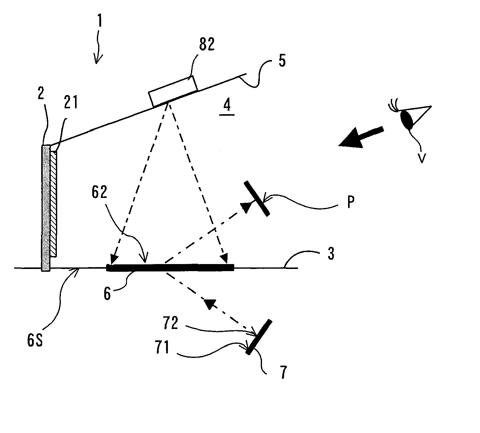
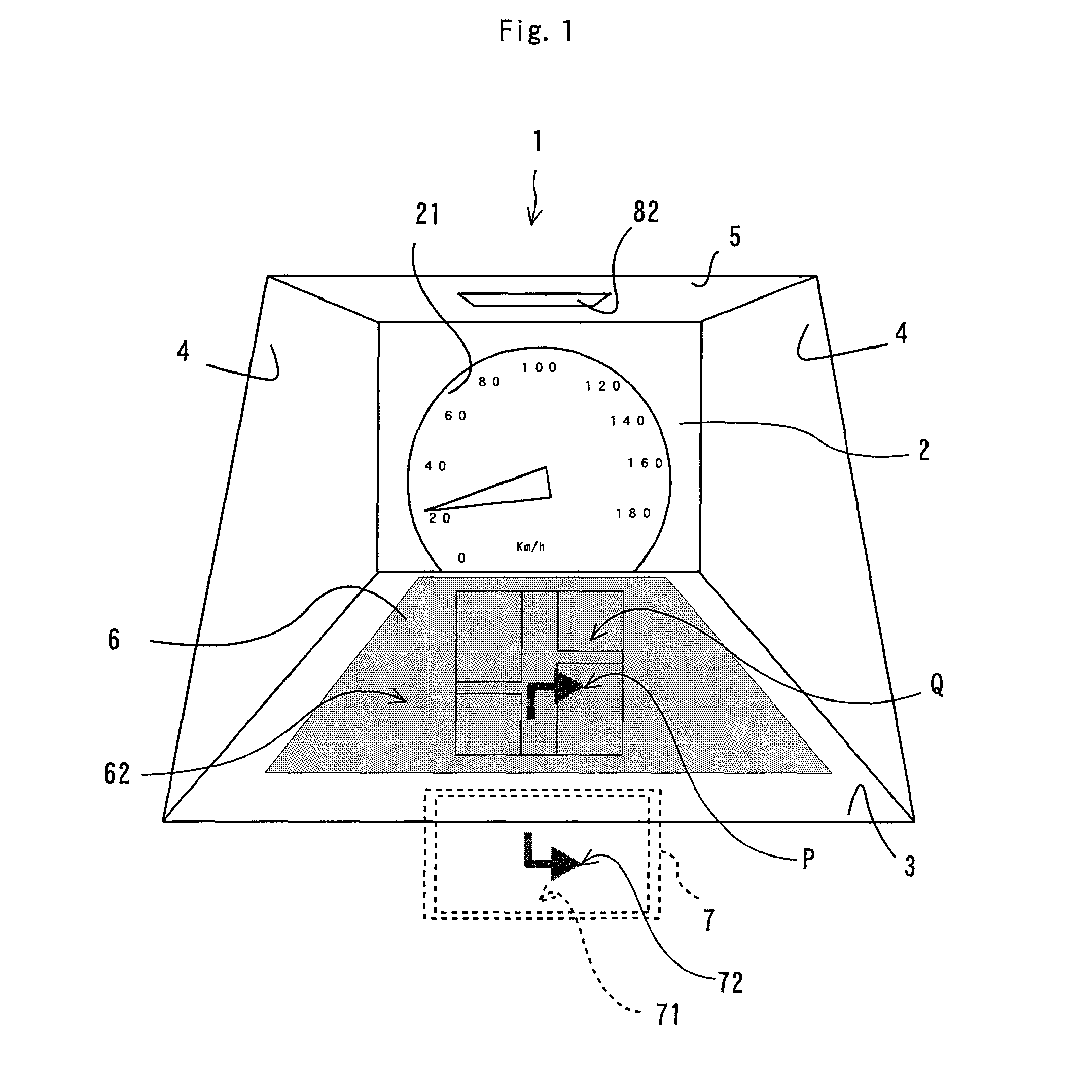
[0045]FIG. 1 is a schematic front view illustrating an instrument panel of a vehicle such as an automobile and its surroundings including a display device 1 of the embodiment of the present invention. FIG. 2 is a schematic sectional and perspective view for explaining the operation of the display device 1.

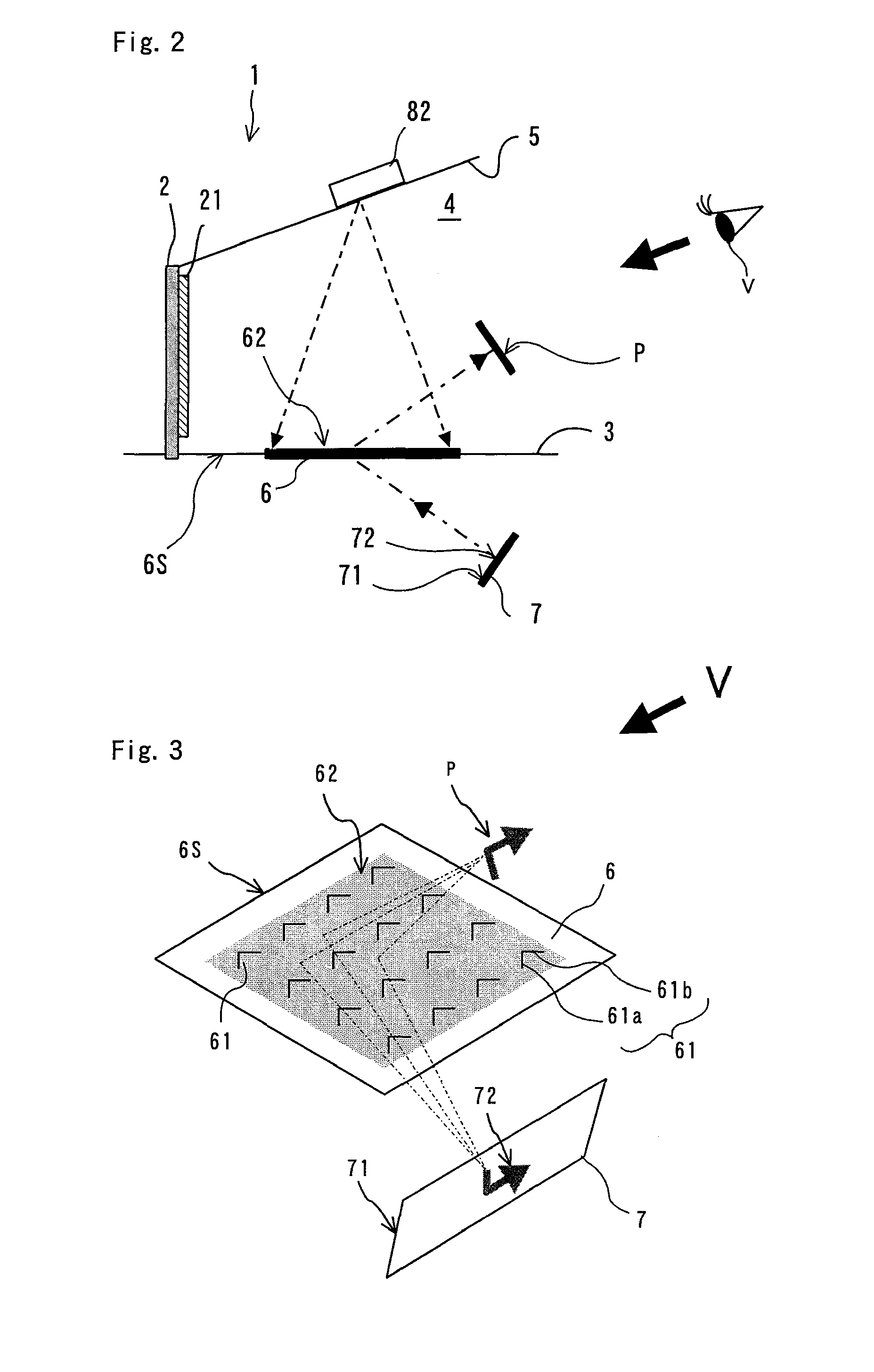
[0046]The display device 1 is made by applying the present invention to an instrument panel and to its surroundings on the driver's side of a transportation machine such as an automobile. Specifically, as shown in FIG. 2, the display device 1 includes a back wall 2 farthest from the viewpoint of a driver as a viewer V, a bottom wall 3, right and left side walls 4, 4, and an upper wall 5 connecting to the back wall 2 and arranged to surround a space in front of the back wall 2 when viewed from the driver, and a display part 21 as a part of the instru...


PUM


Abstract

A display device includes: a wall defining a viewer-side space; an observed object arranged in an object-side space partitioned off the viewer-side space by a portion of the wall; an imaging optical system of real specular image including a semitransparent substrate with a plane of symmetry for defining the viewer-side space and the object-side space as the portion of the wall to image a real image of the observed object in the viewer-side space with light passing through the substrate; a screen surface having a function of diffuse reflection and provided with the substrate so as to face the viewer-side space; and a projector optical system projecting an image on the screen surface in the viewer-side space.

Description

BACKGROUND OF THE INVENTION[0001]1. Field of the Invention[0002]The present invention relates to a display device for allowing a viewer to see a real image of an observed object formed in the air by using an imaging optical system of real specular image.[0003]2. Description of the Related Art[0004]There has been developed a display device using a microlens-array which can visually provide a real image of an observed object such as a displayed image floating in the air to a viewer, for example (see Japanese Published Unexamined Patent Application No. 2001-255493). This display device uses an optical system of an erect equal magnification for a two dimensional image in which spatially parallel translation of the two dimensional image is realized by a display surface displaying a two dimensional image and an optical device having the same size of the display surface so as to optically make a displayed image in the air without distortion. Such configuration is useful for the optical dev...

Claims


Application Information

Patent Timeline
Patent Type & Authority Patents(United States)
IPC IPC(8): G03B21/00G02B27/14G03B21/60G03B21/14G03B21/22G03B21/26G03B21/56
CPCG03B21/28G02B5/136G02B30/56
Inventor SUGIYAMA, TAKASHI
Owner STANLEY ELECTRIC CO LTD
Why Eureka
Try Eureka