Centrifugal pendulum mechanism

A centrifugal force pendulum and pendulum mass technology, applied in springs/shock absorbers, vibration suppression adjustment, mechanical equipment, etc., can solve problems such as damage to the connecting pendulum support, tipping of the pendulum mass pendulum mass bracket, damage to the centrifugal force pendulum function and mode, etc.

Active Publication Date: 2012-10-31
SCHAEFFLER TECH AG & CO KG
View PDF8 Cites 38 Cited by
  • Summary
  • Abstract
  • Description
  • Claims
  • Application Information

AI Technical Summary

Problems solved by technology

However, the resulting relatively large gap distances between the surfaces of the individual pendulum masses pointing towards the pendulum mass support and the pendulum mass support can lead to a tipping of the pendulum mass relative to the pendulum mass support, which is particularly the case at lower rotational speeds and thus Small centrifugal forces will indicate an obvious problem
The functioning of the centrifugal pendulum is therefore impaired in this speed range and cannot be reliably reproduced for recovery conditions
In addition, this tipping can lead to damage to the individual components and the connection of the pendulum mass to the pendulum mass support and its pivot support.

Method used


Image

  • Centrifugal pendulum mechanism
  • Centrifugal pendulum mechanism
  • Centrifugal pendulum mechanism

Examples


Embodiment Construction

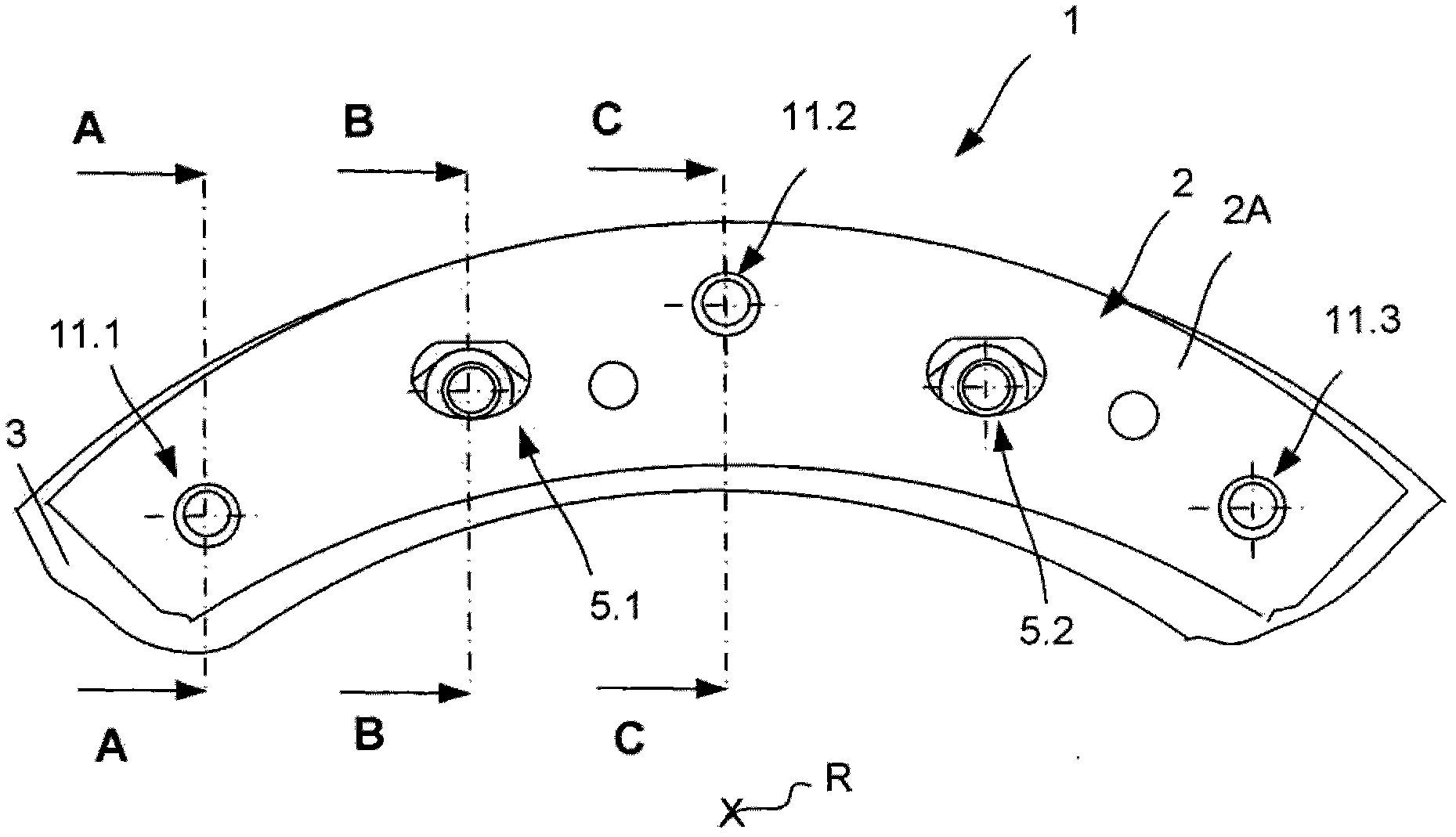
[0058] figure 1 A partial front view of a rotational speed-adapted shock absorber provided according to the invention in the form of a centrifugal pendulum device 1 is shown in schematic diagram. This preferably comprises a plurality of inertial masses acting as pendulum masses 2 , which are mounted movably relative to a rotatable pendulum mass support 3 on the pendulum mass support 3 . The support is implemented pivotally. The pendulum mass support 3 is preferably designed as an annular disk-shaped element. The individual pendulum masses 2 are arranged on the pendulum mass carrier in a uniformly spaced manner as seen in the circumferential direction about the axis of rotation R. FIG. Only pendulum mass 2A of one pendulum mass unit 2 is depicted in the partial diagram of the present presentation. The depiction of the axis of rotation R is only intended to achieve a schematic representation and is not to a correct standard dimension. The inventive support arrangement of the...


PUM


Abstract

The invention relates to a centrifugal pendulum mechanism, comprising at least one pendulum mass support and at least one pendulum mass arranged thereon, which pendulum mass can be moved to a limited extent radially relative to the pendulum mass support by means of at least one rolling element inside raceways formed by recesses in the pendulum mass support and the pendulum mass and in the circumferential direction, the rolling element having a guiding means formed in the gap between the individual pendulum mass and the pendulum mass support.; The invention is characterized in that means for reducing the gap size between the pendulum mass and the pendulum mass support in an at least spatially limited manner are provided outside the raceways for the rolling element and outside the range of the intermediate space between the pendulum mass and the pendulum mass support that can be covered by the guiding means during the rolling motion of the rolling element.

Description

technical field [0001] The invention relates to a centrifugal force pendulum device, comprising at least one pendulum mass support and at least one pendulum mass arranged on the pendulum mass support, which runs on a running track formed by the pendulum mass support and the hollow groove in the pendulum mass support by means of at least one rolling element The inner part is movable to a limited extent in the radial direction and in the circumferential direction relative to the pendulum mass carrier, the rolling element having a guide means formed in the gap between the individual pendulum mass and the pendulum mass carrier. Background technique [0002] Speed-adapted vibration dampers are used in the drive train to damp vibrations over a wide, preferably the entire drive engine speed range. This type makes it possible to damp the rotational oscillations over a large rotational speed range, ideally over the entire rotational speed range of the drive machine, wherein these are...

Claims


Application Information

Patent Timeline
Patent Type & Authority Applications(China)
IPC IPC(8): F16F15/14
CPCF16F15/145Y10T74/2128
Inventor S·迈恩沙因C·许格尔S·容D·施纳德尔巴赫
Owner SCHAEFFLER TECH AG & CO KG
Why Eureka
Try Eureka