Electronic ballast

An electronic ballast, ballast technology, applied in the field of electric lighting

Inactive Publication Date: 2012-11-07
OCEANS KING LIGHTING SCI&TECH CO LTD +1
View PDF6 Cites 10 Cited by
  • Summary
  • Abstract
  • Description
  • Claims
  • Application Information

AI Technical Summary

Problems solved by technology

Or the customer purchased a normal non-dimming ballast and wants to

Method used


Image

  • Electronic ballast
  • Electronic ballast
  • Electronic ballast

Examples


Example Embodiment

[0022] In order to make the objectives, features, and advantages of the present invention more obvious and understandable, the specific embodiments of the present invention will be described in detail below with reference to the accompanying drawings.

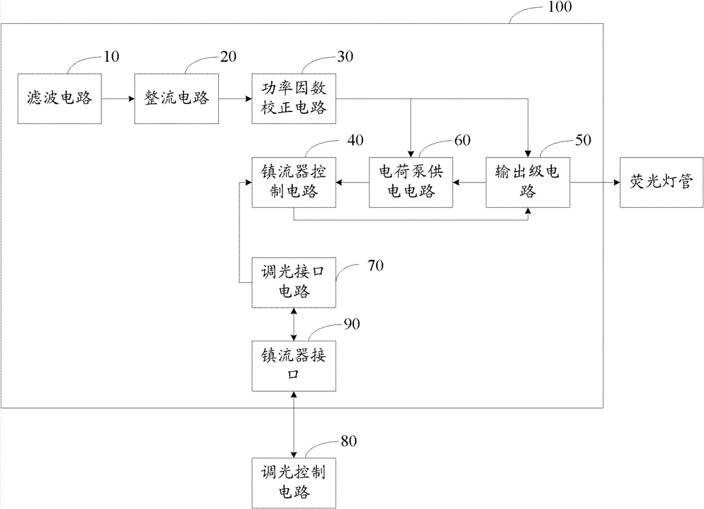
[0023] figure 1 It is a circuit block diagram of an electronic ballast in an embodiment, including a filter circuit 10, a rectifier circuit 20, a power factor correction circuit 30, and a charge pump power supply circuit 60 connected in sequence, and also includes an output stage circuit 50 and a ballast control circuit 40. Dimming interface circuit 70, ballast interface 90, and dimming control circuit 80. The filter circuit 10 filters the input 220 volt AC power and outputs it to the rectifier circuit 20. After the rectifier circuit 20 performs the rectification process, the power factor correction circuit 30 performs power factor correction and outputs 450 volt DC power, which meets electromagnetic compatibility. Performance req...


PUM


Abstract

The invention relates to an electronic ballast. The electronic ballast comprises a filter circuit, a rectifying circuit, a power factor correcting circuit and a charge pump power supply circuit which are sequentially connected, and further comprises an output-level circuit, a ballast control circuit, a light-dimming interface circuit, a ballast interface and a light-dimming control circuit. The output-level circuit is connected between the charge pump power supply circuit and a fluorescent lamp tube. A power source input end is connected with an output end of the charge pump power supply circuit, and a control input end is used for receiving ballast control signals and controlling lighting of the fluorescent lamp tube via the output-level circuit according to the ballast control signals. A control output end is connected with the output-level circuit. The light-dimming interface circuit is connected with the control input end of the ballast control circuit. The ballast interface is connected with the light-dimming interface circuit. The light-dimming control circuit is socketed with the ballast interface and controls light dimming. The light-dimming control circuit is socketed on the ballast interface, so that light dimming is realized. With no need for light dimming, a user can buy the electronic ballast without the light-dimming control circuit independently, and cost is saved.

Description

【Technical field】 [0001] The invention relates to the field of electric lighting, in particular to an electronic ballast. 【Background technique】 [0002] Traditional dimmable electronic ballasts mainly have two forms, one is digital addressable (Digital Adressable Lighting Interface, DALI) dimming electronic ballast, and the other is analog 0-10V dimming electronic ballast device. The above two dimming electronic ballasts are much more expensive than ordinary non-dimming ballasts. In addition, an external DALI controller is required for DALI ballast dimming, and a 0-10V control power supply is required for 0-10V dimming, which is more suitable for building large lighting systems. However, for single lamp dimming or dimming needs with small quantities, the price of dimming accessories is relatively expensive. In addition, the above-mentioned ballast circuits are all made on one circuit board without circuitization, which is not conducive to the expansion of ballast functio...

Claims


Application Information

Patent Timeline
IPC IPC(8): H05B41/298H05B41/38
Inventor 周明杰李英伟
Owner OCEANS KING LIGHTING SCI&TECH CO LTD
Why Eureka
Try Eureka