Novel electronic ballast

An electronic ballast and ballast technology, applied in the electrical field, can solve the problems of inability to adjust lamp brightness, low service life, poor safety performance, etc., and achieve the effects of cost saving, elimination of resonance frequency drift, and flexible resource allocation.

Inactive Publication Date: 2016-05-25
林晓东
View PDF2 Cites 0 Cited by
  • Summary
  • Abstract
  • Description
  • Claims
  • Application Information

AI Technical Summary

Problems solved by technology

[0002] At present, there are several shortcomings in the existing lamp technology: the brightness of the lamp cannot be adjusted, the safety performance is poor, and the service life of the lamp is low.

Method used


Image

  • Novel electronic ballast
  • Novel electronic ballast
  • Novel electronic ballast

Examples


Embodiment Construction

[0019] In order to further understand and recognize the structure, features and effects of the present invention, a preferred embodiment is now given, and detailed descriptions are as follows in conjunction with the accompanying drawings:

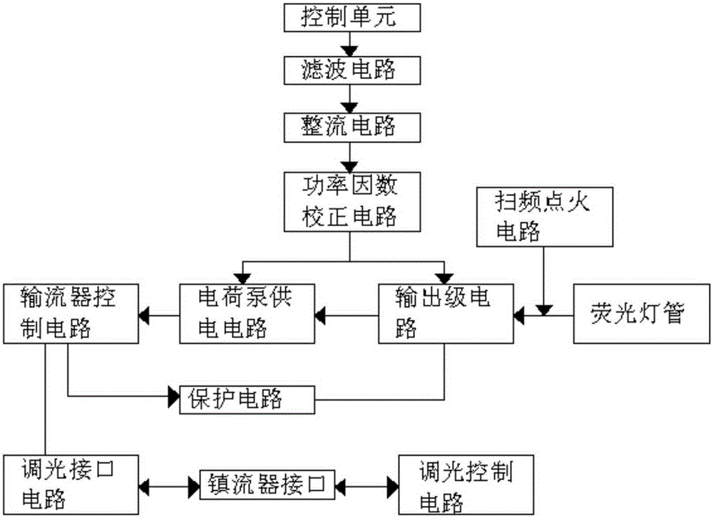
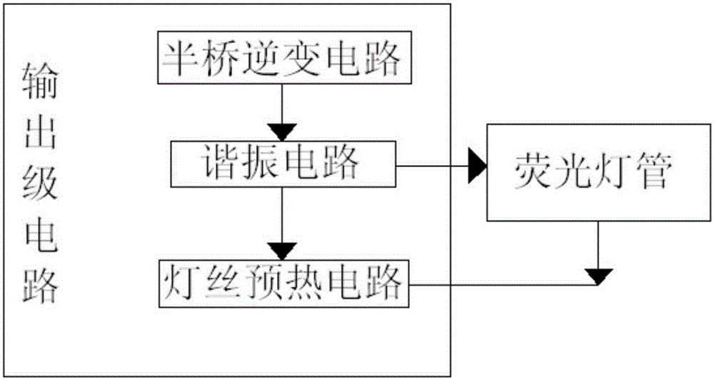
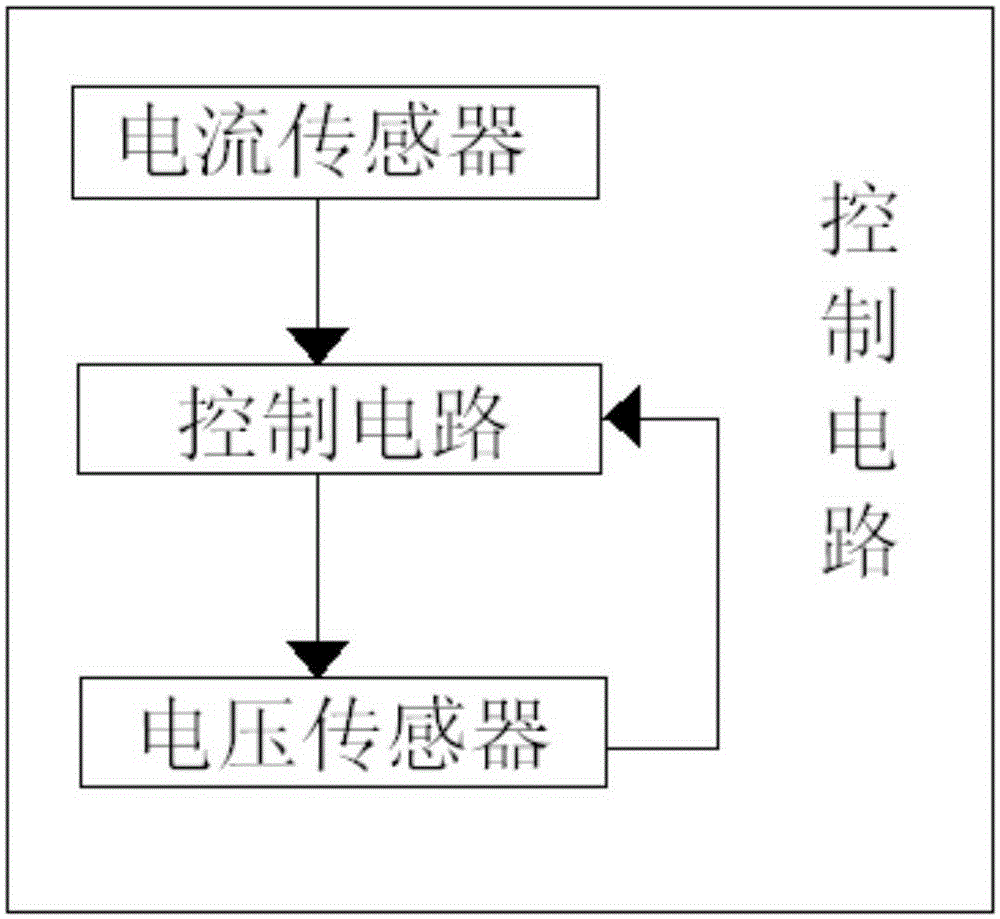
[0020] Such as figure 1 , figure 2 with image 3 As shown, the new electronic ballast described in this embodiment mainly includes a control unit, a filter circuit, a rectifier circuit, a protection circuit, and an output stage circuit. The control unit includes a current sensor, a control circuit, and a voltage sensor. The current sensor and The voltage sensor is used to detect the current and voltage of the load (R0), the control circuit is used to receive the signals of the voltage sensor and the current sensor, and control the operation of the ballast according to the received signal; the output stage circuit includes a half-bridge inverter circuit , a resonant circuit and a filament preheating circuit, the output stage circuit is us...


PUM


Abstract

The invention discloses a novel electronic ballast which comprises a control unit, a filter circuit, a rectification circuit, a protection circuit and an output stage circuit. The control unit is composed of a current sensor, a control circuit and a voltage sensor, the current sensor and the voltage sensor are used to detect the current and voltage of a load (R0) respectively, and the control circuit is used to receive signals of the voltage sensor and the current sensor and control operation of the ballast according to the received signals. According to the novel ballast, a light modulation function is realized, sweep frequency ignition can be used effectively eliminate resonant frequency drift caused by practical device parameter errors, the light modulation function can be used selectively according to practical conditions, resource configuration is more flexible, and the cost is reduced compared to the scheme in which an original electronic ballast needs to be changed to realize the function of light modulation.

Description

technical field [0001] The invention relates to the electrical field, in particular to a novel electronic ballast. Background technique [0002] At present, there are several shortcomings in the existing lamp technology: the brightness of the lamp cannot be adjusted, the safety performance is poor, and the service life of the lamp is low. Through the above shortcomings we need an effective solution. Contents of the invention [0003] The object of the present invention is to provide a novel electronic ballast with adjustable light function and high practicability aiming at the deficiencies of the prior art. [0004] In order to achieve the above object, the present invention is achieved through the following technical solutions: [0005] The new electronic ballast includes a control unit, a filter circuit, a rectifier circuit, a protection circuit and an output stage circuit. The control unit includes a current sensor, a control circuit and a voltage sensor. The current ...

Claims


Application Information

Patent Timeline
Patent Type & Authority Applications(China)
IPC IPC(8): H05B41/295
Inventor 林晓东
Owner 林晓东
Why Eureka
Try Eureka