Plate-fin type heat exchanger with fluid being flowing back and forth in channel

A plate-fin heat exchanger and internal fluid technology, which is applied to the types of heat exchangers, heat exchanger shells, indirect heat exchangers, etc., can solve the problems of low average heat exchange efficiency, increased production costs, and complicated manufacturing processes, etc. problem, to achieve the effect of small space occupation, reduced production cost and simple production process

Active Publication Date: 2013-04-03
TECHNICAL INST OF PHYSICS & CHEMISTRY - CHINESE ACAD OF SCI
View PDF5 Cites 8 Cited by
  • Summary
  • Abstract
  • Description
  • Claims
  • Application Information

AI Technical Summary

Problems solved by technology

Compared with a single plate-fin heat exchanger, the plate-fin heat exchanger group has significant disadvantages in application: the average heat transfer efficiency is low, the production cost is significantly increased, the space is large, the manufacturing process is complicated and difficult, and the service life is longer. Shorter and more prone to failure (more welded joints and connecting pipes)

Method used


Image

  • Plate-fin type heat exchanger with fluid being flowing back and forth in channel
  • Plate-fin type heat exchanger with fluid being flowing back and forth in channel
  • Plate-fin type heat exchanger with fluid being flowing back and forth in channel

Examples


Embodiment 1

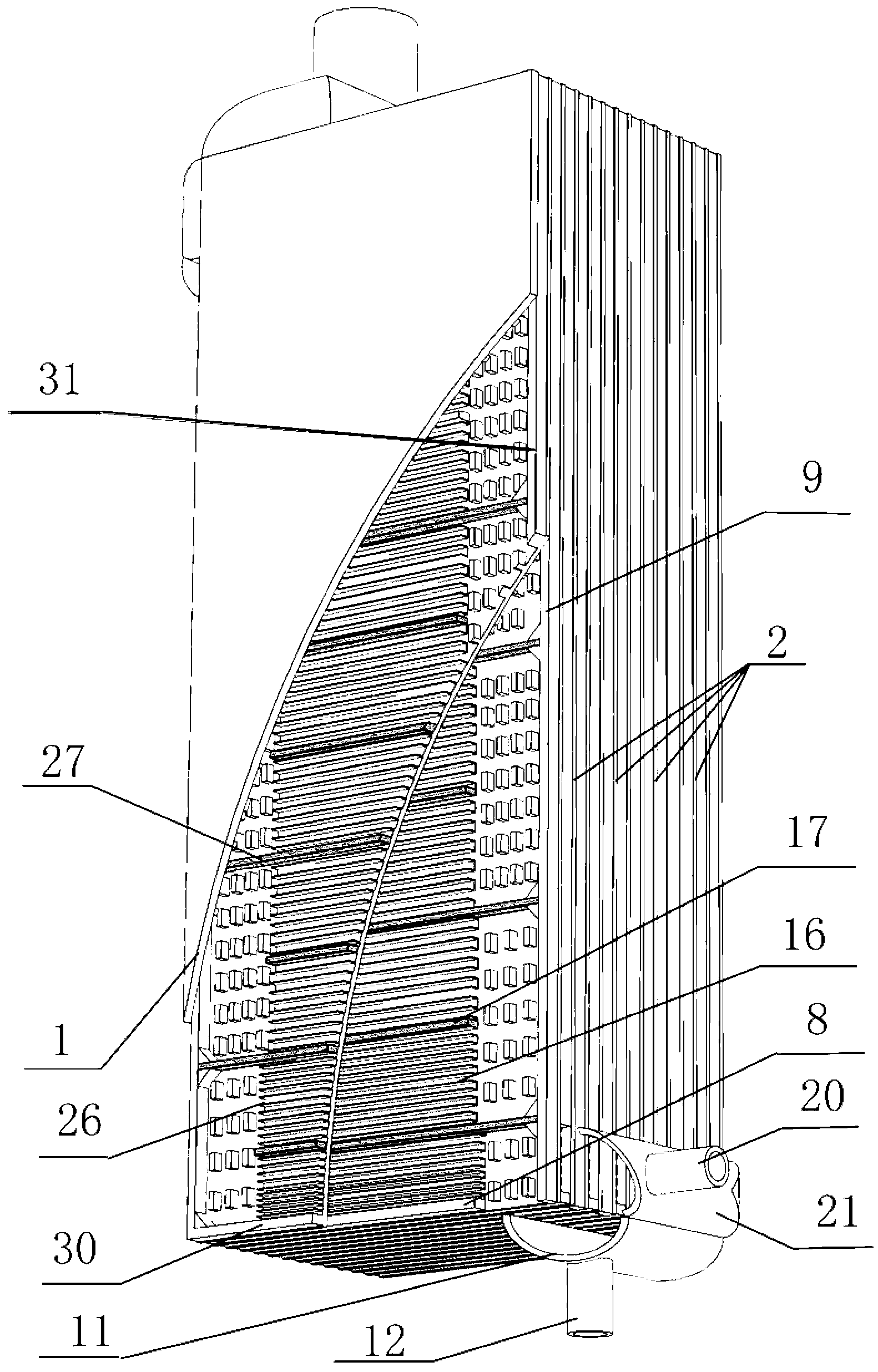
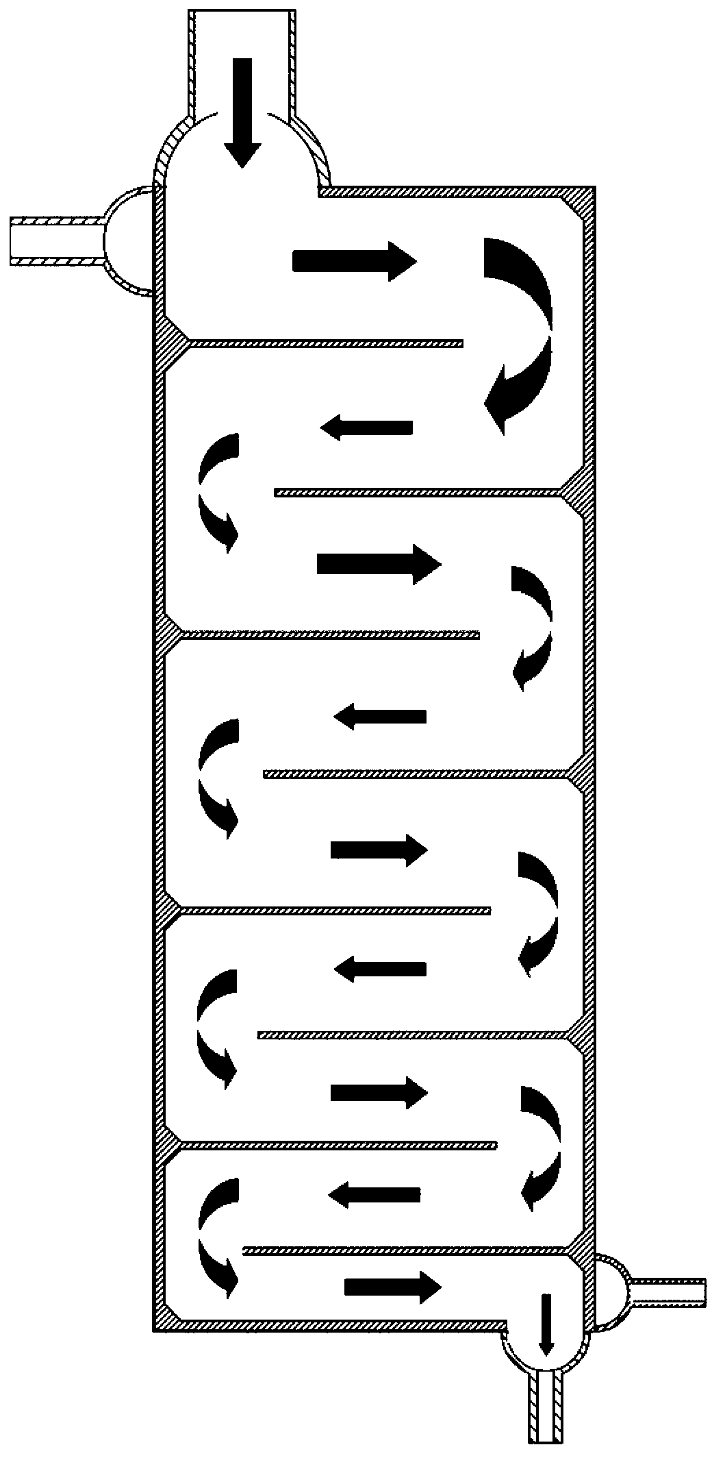
[0040] This embodiment provides a plate-fin heat exchanger, which can be used in a cryogenic multi-component mixed working fluid throttling refrigeration system to realize refrigeration in a 100K temperature zone. See figure 1 , 2 , 3, 4, 5, 6, 9 and Figure 10 , a plate-fin heat exchanger in which the fluid in the channel turns back and flows, which includes:

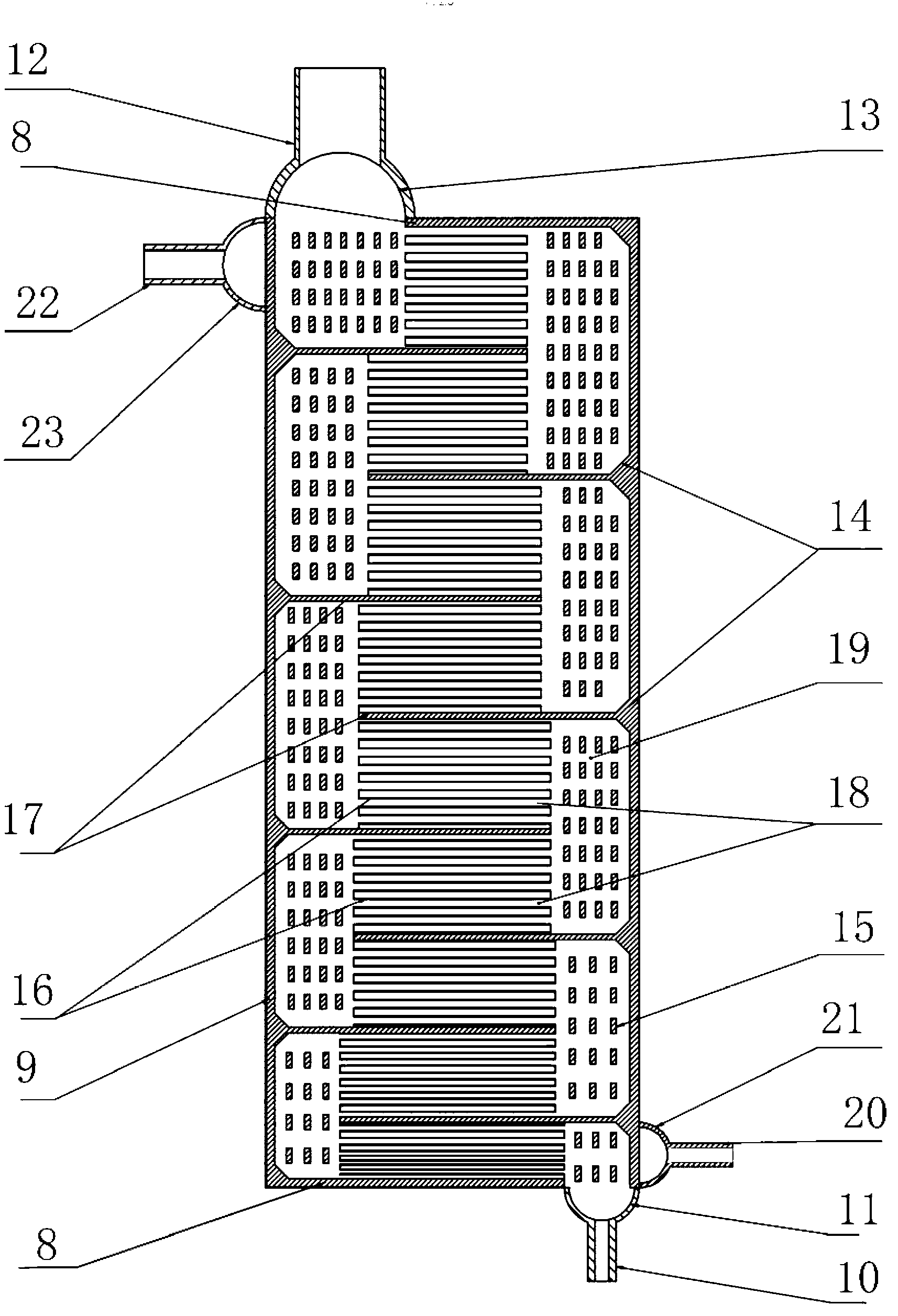
[0041] A heat exchanger shell 1 composed of left and right vertical shell plates; a vertical channel partition 2 placed between the left and right vertical shell plates at intervals; the left and right vertical shell plates are adjacent to it Horizontal edge seals and left and right vertical edge seals are respectively provided at the peripheral edges between the vertical channel partitions 2 of adjacent channels and the peripheral edges between the vertical channel partitions 2 of adjacent channels to form heat exchange channels; The heat exchange channels are divided into hot channels and cold channels distributed...

Embodiment 2

[0053] Embodiment 2: A plate-fin heat exchanger related to the present invention is used in a large-scale natural gas liquefaction refrigeration system to realize natural gas liquefaction.

[0054] It is basically the same as that of Example 1, the difference is that in each cold channel in the heat exchanger, 6 horizontally placed cold runner horizontal adjustment slats are set to divide the channel into 7 horizontal runners and 6 vertical runners. In each hot channel of the heat exchanger, 5 horizontally placed hot runner horizontal adjustment strips are set to divide the channel into a return channel composed of 6 horizontal channels and 5 vertical channels. Shaped runner. Among the 7 horizontal flow channels in the cold aisle, except for the bottom 3, the other 4 horizontal flow channels are all equipped with horizontal serrated fins with the same wing pitch, and the bottom 3 flow channels are each equipped with The fin group composed of 4 kinds of fins with different pit...

Embodiment 3

[0056] Embodiment 3: A plate-fin heat exchanger related to the present invention is used in a large-scale natural gas liquefaction refrigeration system to realize natural gas liquefaction.

[0057] It is basically the same as Embodiment 1, the difference is: a square dispersion fin is set in the vertical flow channel of the cold aisle and the hot aisle, such as Figure 7 , which is conducive to the uniform distribution of fluid in the flow channel.


PUM


Abstract

The invention relates to a plate-fin type heat exchanger with fluid being flowing back and forth in a channel. Cold channels and hot channels inside the plate-fin type heat exchanger are arranged in a layered and crossed manner and are separated by channel clapboards, and heat transfer fins are arranged in the channels; one or more horizontal adjusting battens which are horizontally arranged are arranged in each channel of the heat exchanger to separate the channel into a plurality of horizontal flow passes in the height direction; the horizontal flow passes are connected in series end to end by vertical flow passes in each channel; fluid participating in heat exchanger flows through each horizontal flow pass and each vertical flow pass in sequence to form repeated back-and-forth flow in each channel; through setting the widths of each horizontal flow pass and each vertical flow pass in each channel, the plate-fin type heat exchanger is easy to enable the fluid in each channel to keep in a reasonable range; and even if the fluid is subjected to phase change in the heat exchanger to cause that the volume and the flow rate of an inlet are very remarkably different from those of an outlet, and the reasonable flow rate distribution can be achieved by using the plate-fin type heat exchanger. The plate-fin type heat exchanger has the advantages of easily realizing flow rate regulation and distribution of the fluid, improving the efficiency of the heat changer, saving the occupied space and remarkably lowering the manufacturing cost.

Description

technical field [0001] The invention relates to a plate-fin heat exchanger, in particular to a plate-fin heat exchanger in which a fluid in a channel turns back and flows. Background technique [0002] The plate-fin heat exchanger has the characteristics of compact structure and high heat transfer efficiency. Compared with the traditional shell-and-tube heat exchanger, its heat transfer efficiency is increased by 20-30%, and the cost can be reduced by 50%. It has been widely used in air Separation, petrochemical, aerospace and other fields. The existing plate-fin heat exchanger is mainly composed of the shell, the inner channel of the heat exchanger, the partition plate of the heat exchanger channel, the fins arranged in the direction of the main flow in each channel, the outer edge seals of each channel, and the welded joints at both ends of the heat exchanger. The head cavity, the inlet pipe and the outlet pipe on the head cavity are welded. Its internal channel is separ...

Claims


Application Information

Patent Timeline
Patent Type & Authority Applications(China)
IPC IPC(8): F28D9/00F28F9/02F28F9/22
Inventor 公茂琼吴剑峰陈高飞董学强
Owner TECHNICAL INST OF PHYSICS & CHEMISTRY - CHINESE ACAD OF SCI
Why Eureka
Try Eureka