Fluorescence detection system and cell analyzer

A fluorescence detection and fluorescence technology, which is applied in the field of optical systems for collecting fluorescence, can solve problems such as high cost, differences in filter batch parameters, instrument consistency, and accuracy effects, and achieve convenient collection, good cost advantages, and overall Simple and compact structure

Active Publication Date: 2013-05-08
SHENZHEN MINDRAY BIO MEDICAL ELECTRONICS CO LTD +1
View PDF5 Cites 16 Cited by
  • Summary
  • Abstract
  • Description
  • Claims
  • Application Information

AI Technical Summary

Problems solved by technology

Because different fluorescence corresponds to different wavelengths, the coating parameters of dichroic mirrors and bandpass filters are generally very high for detection accuracy. Only one layer of coating can meet the requirements, so the coating of optical filters used in flow cytometry is difficult and costly, and there are differences in parameters between batches of optical filters, which will have a great impact on the consistency and accuracy of the instrument In addition, the fluorescence signal of each channel is collected by using this combination of filter and dichroic mirror. Once the combination of filter and dichromatic mirror is fixed, the filter cannot be replaced, and the fluorescence band emitted by the particles cannot be adjusted. , there is a lack of flexibility for users with higher requirements, and users cannot choose the fluorescence band of interest at will

Method used


Image

  • Fluorescence detection system and cell analyzer
  • Fluorescence detection system and cell analyzer
  • Fluorescence detection system and cell analyzer

Examples


Embodiment Construction

[0020] The present invention will be further described in detail below through specific embodiments in conjunction with the accompanying drawings.

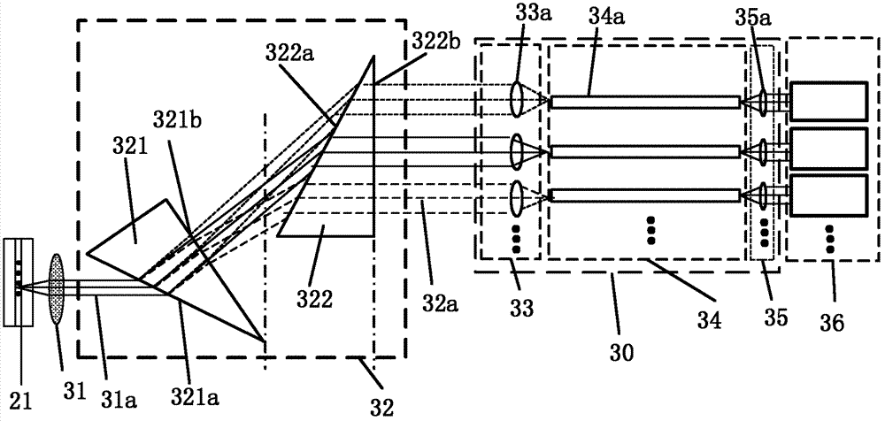
[0021] First, explain the prism. A prism generally refers to a transparent object surrounded by two intersecting planes that are not parallel to each other. The light is incident from one surface and exits from the other surface. , and the edges may not be limited to three, such as cutting off a corner to become four sides, etc.

[0022] The core of the present invention is to propose a fluorescence detection system using a double prism to split light. The fluorescence detection system utilizes the prism material to have a dispersion and light splitting function for light wavelengths of 0.5-0.9 μm. The light is output and the spot of the beam is multiplied and enlarged. When a beam of fluorescence signals containing each wavelength is emitted through the fluorescence detection system, the fluorescence of each wavelength will be a...


PUM

PropertyMeasurementUnit
refractive indexaaaaaaaaaa
Abbe numberaaaaaaaaaa

Abstract

The invention discloses a fluorescence detection system and a cell analyzer adopting the fluorescence detection system. The fluorescence detection system comprises a fluorescence collection object lens, a spectroscope, a fluorescence transmission channel and a detector unit. The spectroscope comprises a first double-prism assembly comprising a first prism and a second prism. Parallel light aligned by the fluorescence collection object lens irradiates a first incident surface of the first prism. A second exit surface of the second prism is perpendicular to an optical axis of the fluorescence collection object lens. The first prism is arranged in a way so that incident parallel light is reflected by the first prism and the second prism, then is divided into multiple parallel lights which have different wavelengths and are parallel to the incident parallel light, and then exit from the second exit surface. The fluorescence detection system can flexibly satisfy wave band demands and is convenient for fluorescence collection in subsequent channels. The number of the fluorescence transmission channels can be flexibly adjusted according to actual requirements.

Description

technical field [0001] The invention relates to the field of particle analysis, in particular to an optical system for collecting fluorescence in particle analysis. Background technique [0002] In the medical and biological fields, flow cytometers are usually used to count and analyze tiny particles such as cells, DNA, proteins and various enzymes. Or other biological particles for quantitative analysis and sorting detection means, can analyze thousands of cells at high speed, and can measure multiple parameters from one cell at the same time. The flow cytometer stains the particles to be detected with fluorescent reagents, so that the particles are wrapped in the sheath fluid to form a sample flow through the detection area, and the particles to be detected that flow through the detection area are irradiated with laser light, and different types of particles to be detected emit light of different wavelengths. Fluorescence, which is collected by an optical detection system...

Claims


Application Information

Patent Timeline
Patent Type & Authority Applications(China)
IPC IPC(8): G01N15/00G01N15/14
Inventor 梁敏勇史宏伟安栋梁
Owner SHENZHEN MINDRAY BIO MEDICAL ELECTRONICS CO LTD
Why Eureka
Try Eureka