Supercharge Your Innovation With Domain-Expert AI Agents!

Method for preparing yarn ends for spinning-in by an open-end rotor spinning machine and spinning rotor

A technology of rotor spinning machine and free end, which is applied in the field of yarn end, and can solve the problems of increasing the complexity of the spinning unit and increasing the production cost, etc.

Active Publication Date: 2016-09-28
RIETER CZ AS
View PDF4 Cites 0 Cited by
  • Summary
  • Abstract
  • Description
  • Claims
  • Application Information

AI Technical Summary

Problems solved by technology

However, this is a complex method requiring the spinning unit to be equipped with many additional devices supporting its implementation, which increases the complexity of the spinning unit and thus increases the production costs

Method used


Image

  • Method for preparing yarn ends for spinning-in by an open-end rotor spinning machine and spinning rotor
  • Method for preparing yarn ends for spinning-in by an open-end rotor spinning machine and spinning rotor
  • Method for preparing yarn ends for spinning-in by an open-end rotor spinning machine and spinning rotor

Examples


Embodiment Construction

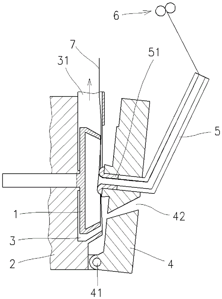
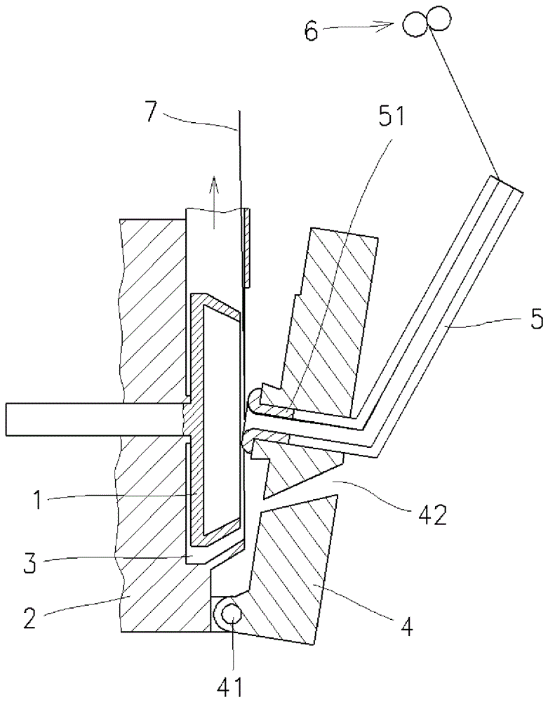
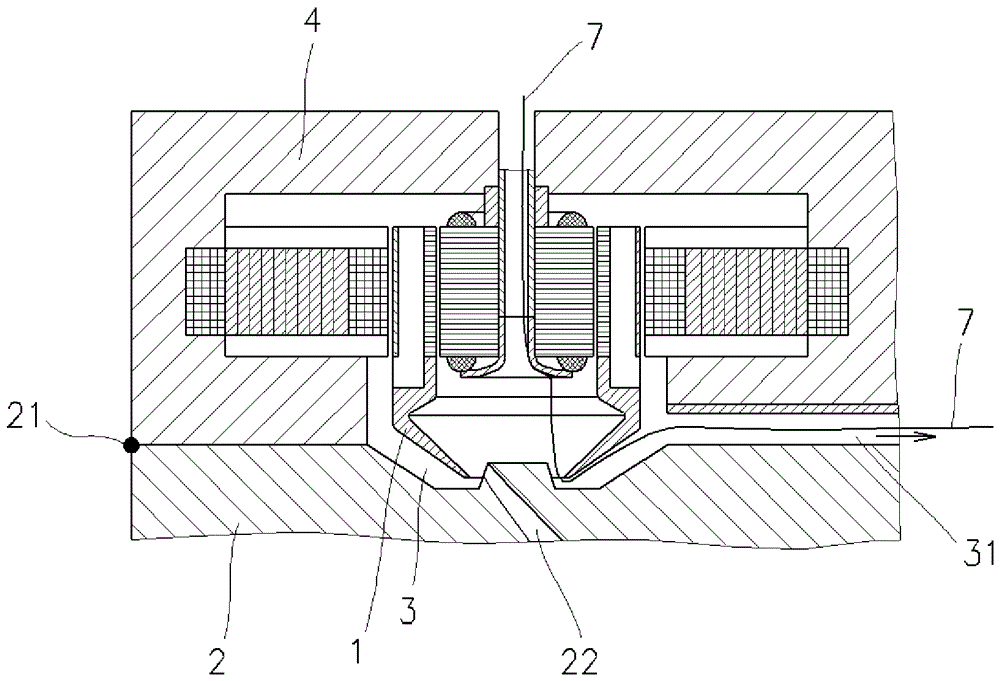
[0020] will be about Figure 1-Figure 3 A single spinning unit of an open-end rotor spinning machine is shown schematically to illustrate the method according to the invention for preparing a yarn end for spinning-in from an open-end rotor spinning machine.

[0021] The spinning unit of an open-end rotor spinning machine comprises a spinning rotor 1 placed in the main body 2 of the spinning unit and coupled to a not shown drive in a not shown rotational manner known to those skilled in the art. The rotor cup 1 comprises a body without ventilation holes and is placed in a vacuum chamber 3 which is connected by a vacuum channel 31 to a not shown vacuum source known to a person skilled in the art. In the application shown, the vacuum chamber 3 is formed in the main body 2 of the spinning unit and is on the outside in its operative position closed by a cover 4 which is removably placed on the main body of the spinning unit, for example by pins 41 2 on. In the cover 4, a channel ...


PUM


Abstract

The invention relates to a method for preparing yarn ends for spinning-in by an open-end rotor spinning machine comprising a spinning rotor placed in a vacuum chamber by means of a vacuum The channel is connected to a vacuum source. The yarn is sucked into the vacuum channel through the drawing tube with the nozzle, whereupon the yarn is cut between the nozzle and the vacuum channel by means of the edge of the rotating rotor, thereby forming the end of the introduced yarn ready for spinning-in. The edges of the entry opening of the spinning rotor are roughened to facilitate yarn regrinding.

Description

technical field [0001] The invention relates to a method for preparing yarn ends for spinning-in from an open-end rotor spinning machine comprising a spinning rotor placed in a vacuum chamber, wherein the vacuum chamber Connect to a vacuum source via the vacuum channel. [0002] The invention also relates to a spinning rotor. Background technique [0003] Every time the spinning is rebuilt, i.e. at every spinning-in through the open-end rotor spinning machine, at the start of spinning or at any subsequent technical cut-off in the process of producing the yarn, preparation for a new spinning-in is required end of the yarn. It is then necessary to measure the required yarn length and modify its ends in an appropriate manner in order to achieve the highest possible quality of the spin-in. Subsequently, the end of the yarn is dropped onto the collecting groove of the spinning rotor, and after it is bonded to the fiber strip, yarn pulling is started and wound on the mandrel. ...

Claims


Application Information

Patent Timeline
Patent Type & Authority Patents(China)
IPC IPC(8): D01H4/48D01H4/10
CPCD01H4/40
Inventor M.弗克尔J.库特尔瓦斯尔J.斯劳彭斯基
Owner RIETER CZ AS
Features
  • R&D
  • Intellectual Property
  • Life Sciences
  • Materials
  • Tech Scout
  • Unparalleled Data Quality
  • Higher Quality Content
  • 60% Fewer Hallucinations
Learn More