Hydrodynamic retarder

A hydraulic retarder and oil technology, applied in the direction of hydraulic resistance brakes, brake types, mechanical equipment, etc., can solve the casting and processing difficulties of oblique straight blades, the low working efficiency of hydraulic retarders, and the waste products generated by demoulding. It can increase the braking effect, take up less space and have a solid structure.

Inactive Publication Date: 2013-07-03
西安双特智能传动有限公司
View PDF6 Cites 2 Cited by
  • Summary
  • Abstract
  • Description
  • Claims
  • Application Information

AI Technical Summary

Problems solved by technology

[0024] like Figure 4 As shown, in order to increase the braking torque, the hydraulic retarder of the existing design adopts the form of oblique and straight blades, which can give full play to the actual fluid flow after the integration of the circular flow and the eddy current, and increase the braking effect, but the oblique blade casting And processing is very difficult, the casting mold is complicated, and the scrap rate of demoulding is high, which is not conducive to the reduction of product cost; at the same time, the casting connection area between the inclined and straight blades and the fixed wheel and the runner is small, and the oil hits the blade at high speed when the moving wheel is running fast. The impact force on the blade is large. Due to the vibration and fatigue caused by the hydraulic impact, the blade is often interrupted. The damage rate of the blade is high, resulting in low working efficiency of the hydraulic retarder, or even failure to work normally.

Method used


Image

  • Hydrodynamic retarder
  • Hydrodynamic retarder
  • Hydrodynamic retarder

Examples


Embodiment Construction

[0050] The present invention is described in detail below in conjunction with accompanying drawing:

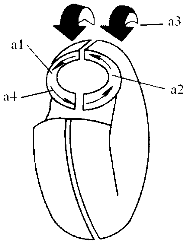
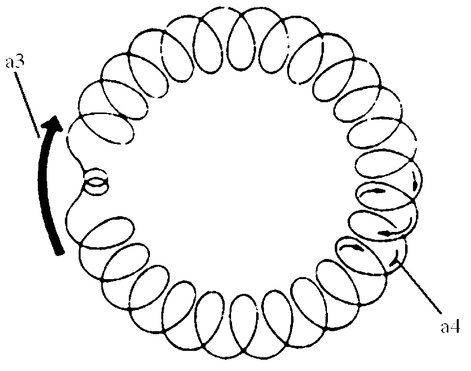
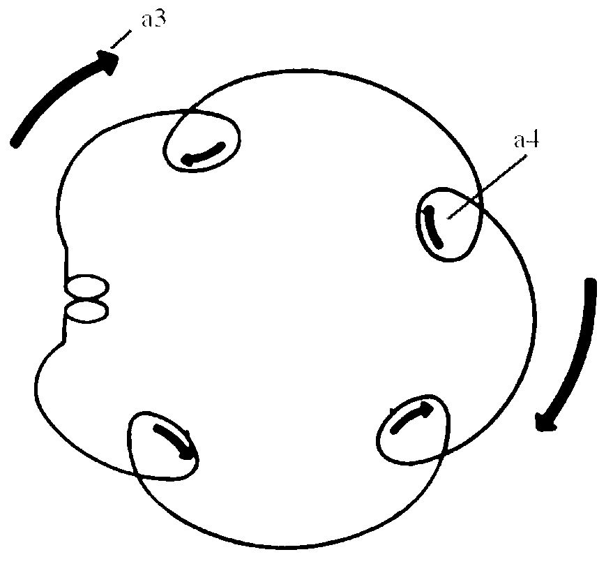
[0051] Such as Figure 5 and Figure 6As shown, the present invention discloses a hydraulic retarder, which includes a runner and a fixed wheel. The blades of the runner and the fixed wheel are arranged along the radial direction of the runner and the fixed wheel, and the two sides of the straight blades are inclined to collect oil. The U-shaped blades of the runner and the fixed wheel are set opposite to each other. The thickness of the front end of the blade is small and the middle thickness is large, and the front end is provided with a draft angle 4. The blades are divided into upper surface 2, front surface 1 and rear surface 3. The surface that impacts on the front of the liquid flow is the front surface 1, the surface opposite to the front surface 1 is the rear surface 3, and the upper part of the blade is the upper surface 2; the upper surface 2 of the blade is an arc...


PUM


Abstract

The invention provides a hydrodynamic retarder. The hydrodynamic retarder comprises a turning wheel and a fixed wheel, wherein blades of the turning wheel and the fixed wheel are U-shaped and are arranged along the radial directions of the turning wheel and the fixed wheel; the U-shaped blades of the turning wheel and the fixed wheel are arranged in opposite directions; oil fluids in an inner ring and an outer ring of a hydrodynamic circulating cavity are fully centralized to a place with the largest axial hydrodynamic circulating circle for impacting and stirring; the front end of each blade is thin and the middle part of each blade is thick; a taper oblique angle is formed at the front end of each blade; the upper surface of each blade is an arc-shaped; the semicircular arc-shaped surface on the upper surface of the two U-shaped blades arranged in opposite directions forms another circulating circle between the turning wheel and the fixed wheel; stirring circulating impact can be carried out on the upper part of the blade to further enhance mutual impact of liquid flow; the casting connection area between the U-shaped blades, the fixed wheel and the turning wheel is large; the two sides of eawch blade are similar to two support ribs so as to enhance the rigidity of the blades; the structure is firm and unlikely to be damaged; and by increasing the diameter of the circulating circle, the axial size of the whole transmission is reduced, the occupation space is small, and the casting difficulty is low.

Description

technical field [0001] The invention belongs to the field of automobiles and relates to a hydraulic retarder. Background technique [0002] Commercial vehicles and engineering vehicles often work in different road environments. With the improvement of the power system capacity of today, the load of commercial vehicles is getting heavier and the driving speed is getting higher and higher. However, the size of existing vehicles and the brake drum and The diameter of the tires does not change, which puts forward higher requirements for the braking system of commercial vehicles; as people pay more and more attention to safety, in addition to driving brakes for commercial vehicles such as passenger cars, the installation of auxiliary braking devices is also required. more and more necessary. [0003] The hydraulic coupler and the hydraulic retarder use the liquid as the working medium, and use the hydrodynamic transmission, that is, the power is transmitted through the change of...

Claims


Application Information

Patent Timeline
Patent Type & Authority Applications(China)
IPC IPC(8): F16D57/02
Inventor 王军柯瓦泽王亚锋王凯峰芮井中赵会强伏春乾毕乾坤
Owner 西安双特智能传动有限公司
Why Eureka
Try Eureka