
Ignition switch with car key pull-forgetting prevention function
An ignition switch, car key technology, applied in the direction of electric switch, contact surface shape/structure, electrical components, etc., can solve the problems of increasing the complexity of the lock body, high cost, reducing the reliability of the lock body, etc. Simple, improved service life, high reliability
- Summary
- Abstract
- Description
- Claims
- Application Information
AI Technical Summary
Problems solved by technology
Method used
Image

Examples
Embodiment
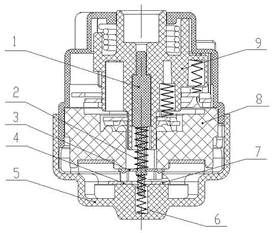
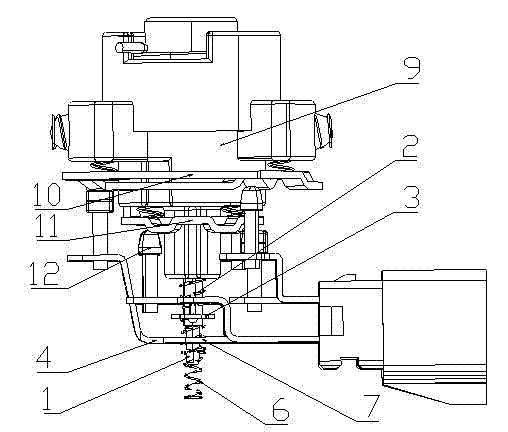
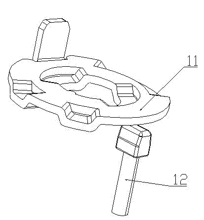
[0020] Such as figure 1 , there is a square hole at the top of the rotating shaft 9, which is used to install the interlocking pin of the lock body. There are two metal turntables installed on the outside of the rotating shaft 9. The upper end is a large turntable 10, and the corresponding three contact columns 12 are respectively connected to the IG1 terminal. contact piece, ACC terminal contact piece and common terminal contact piece 4 (B1), the lower end is a small turntable 11, and the corresponding two contact columns 12 are respectively connected to the ST (ignition) terminal contact piece and the IG2 terminal contact piece . A push rod 1 is arranged in the middle of the rotating shaft 9, which is in contact with the push rod in the linkage pin. The movable contact piece 3 is installed on the push rod 1, and the contact at one end of the movable contact piece 3 corresponds to the common terminal contact piece 4, and the contact piece at the other end Corresponding to t...
PUM
 Abstract
Description
Claims
Application Information