A protective material resistance to cold and heat pulse fatigue test device

A technology for protective materials and fatigue testing, applied in measuring devices, analyzing materials, using mechanical devices, etc., can solve problems such as unsatisfactory experimental equipment, and achieve fast cold and heat exchange time, high temperature control accuracy, and good temperature uniformity. Effect

Inactive Publication Date: 2016-04-06
INST OF METAL RESEARCH - CHINESE ACAD OF SCI
View PDF9 Cites 0 Cited by
  • Summary
  • Abstract
  • Description
  • Claims
  • Application Information

AI Technical Summary

Problems solved by technology

[0005] In the existing test technology, the experimental equipment for high-low temperature cold and hot rapid cycle is not ideal. Therefore, people expect to obtain a protective material anti-cold and hot pulse fatigue test device with better technical evaluation effect.

Method used


Image

  • A protective material resistance to cold and heat pulse fatigue test device
  • A protective material resistance to cold and heat pulse fatigue test device
  • A protective material resistance to cold and heat pulse fatigue test device

Examples


Embodiment 1

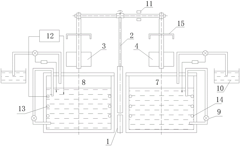
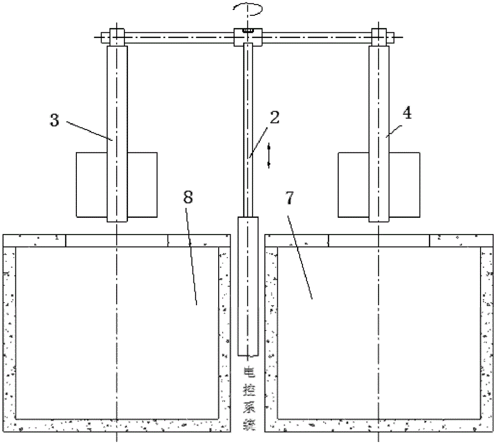
[0038] Such as figure 1 , 2 shows the coating anti-high-frequency thermal pulse fatigue test device, which includes an electric control system 1, a lifting and rotating device 2, two special sample holders: sample holder A3 and sample holder B4, two test tanks: high temperature tank 7 and low temperature tank 8.

[0039] The sample rack A3 and the sample rack B4 are respectively vertically fixed on the left and right supports of the lifting and rotating device. The electric control system 1 automatically controls the cylinder lifting and rotating device 2 to drive the sample holder A3 and the sample holder B4 of the two coated samples (6) to perform upward, downward and counterclockwise high-frequency rotation movements. The low temperature tank 8 and the high temperature tank 7 are located vertically below the two sample racks.

[0040] Description of working process:

[0041] Start the heating and condensing device before the experiment starts, then set the temperature of...

Embodiment 2

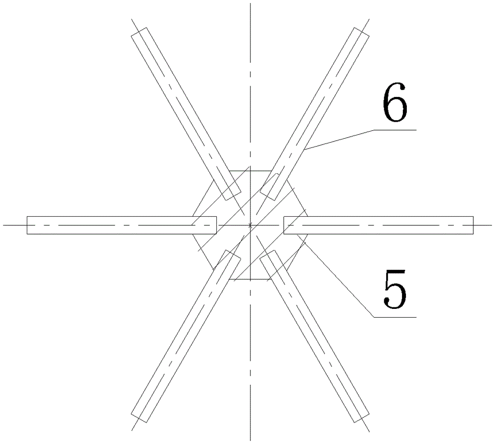
[0043] A protective material anti-cold and heat pulse fatigue test device, the protective material anti-cold and heat pulse fatigue test device specifically includes the following structure: an electric control system 1 and a lifting and rotating device 2, two sample holders, namely sample holder A3 and sample Rack B4, test tank; wherein: the electric control system 1 and the lifting and rotating device 2 are connected as a whole; the rotating axis is fixedly arranged on the lifting and rotating device 2 arranged in the vertical direction, and a sample rack is fixedly arranged on the sample rack for placing samples. 6 for sample slot 5;

[0044] The test tank for containing the sample 6 is arranged below the rotation path of the sample holder outside the rotation axis of the lifting and rotating device 2 .

[0045] The protective material resistance to cold and heat pulse fatigue test device described in this embodiment also includes the following content requirements:

[004...

Embodiment 3

[0057] The content of this embodiment is basically the same as that of Embodiment 2, the difference is that:

[0058] Two sample slots 5 are fixedly arranged on the sample rack A3 and the sample rack B4.


PUM


Abstract

A protection material hot-cold pulse fatigue resistance test apparatus includes an electric control system (1), an elevating rotation device (2), sample supports and test tanks wherein the electric control system (1) and the elevating rotation device (2) are connected into one; the sample supports are fixedly arranged on the elevating rotation device (2) having a rotary axis arranged in the vertical direction, and sample slots (5) used for disposing a sample (6) are fixedly arranged on the sample supports; and the test tanks used for disposing the sample (6) are arranged below the rotation paths of the sample supports outside the rotary axis of the elevating rotation device (2). The apparatus has the advantages of high automation degree, good temperature stability and excellent technological effects.

Description

technical field [0001] The invention relates to the technical field of structural design and application of a protective material rapid evaluation experiment device, and in particular provides a protective material anti-cold and heat pulse fatigue test device. Background technique [0002] In the prior art, the inner walls of pipeline heat exchange transportation systems for oil, gas, and water-liquid systems, including pump bodies, valves and other accessories, are generally protected by lining protective materials to prevent corrosion and wear of the inner wall transportation medium. Since the temperature of the liquid medium conveyed inside the heat exchange system generally fluctuates continuously within the range of -25°C to 100°C, the short-term temperature difference reaches 20°C to 100°C, and the temperature change cycle of the rapid cold and heat alternation is ≥10 seconds. There is an urgent need to develop a test device that can simulate the above-mentioned use en...

Claims


Application Information

Patent Timeline
Patent Type & Authority Patents(China)
IPC IPC(8): G01N17/00G01N19/04
Inventor 陆卫中高英郭旭李京张立新史杰智李晓东刘宝昌
Owner INST OF METAL RESEARCH - CHINESE ACAD OF SCI
Why Eureka
Try Eureka