Engine EGR (Exhaust Gas Recirculation) system

An engine and EGR valve technology, applied in engine components, combustion engines, machines/engines, etc., can solve problems such as inability to determine cooling efficiency, engine emissions exceeding the limit, and reduction in cooling efficiency of EGR coolers, and achieve real-time monitoring of cooling efficiency, Avoid carbon deposition, simple and reasonable structure

Inactive Publication Date: 2014-01-01
GUANGXI YUCHAI MASCH CO LTD
View PDF6 Cites 15 Cited by
  • Summary
  • Abstract
  • Description
  • Claims
  • Application Information

AI Technical Summary

Problems solved by technology

Tests have shown that the cooling efficiency of the EGR cooler will decrease with time, and the existing system cannot judge its cooling efficiency, which will increase the risk of engine emission exceeding the limit

Method used


Image

  • Engine EGR (Exhaust Gas Recirculation) system
  • Engine EGR (Exhaust Gas Recirculation) system

Examples


Embodiment Construction

[0024] A specific embodiment of the present invention will be described in detail below in conjunction with the accompanying drawings, but it should be understood that the protection scope of the present invention is not limited by the specific embodiment. It should be understood that the "upper", "lower", "left", "right", "front" and "reverse" mentioned in the following embodiments of the present invention are all based on the directions shown in the figures, These words used to limit the direction are only for convenience of description, and do not mean to limit the specific technical solution of the present invention.

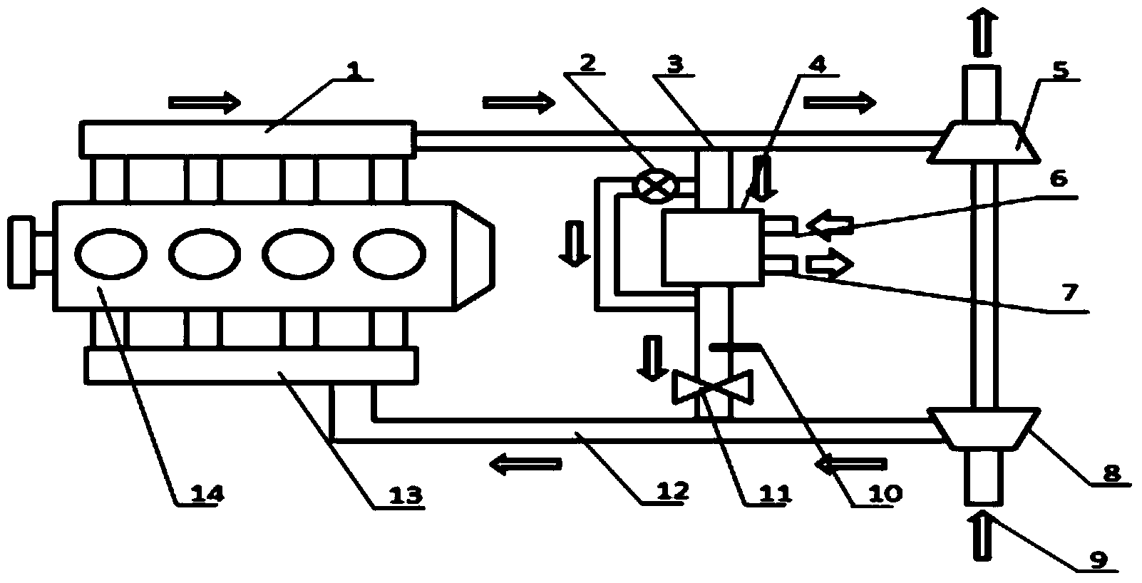
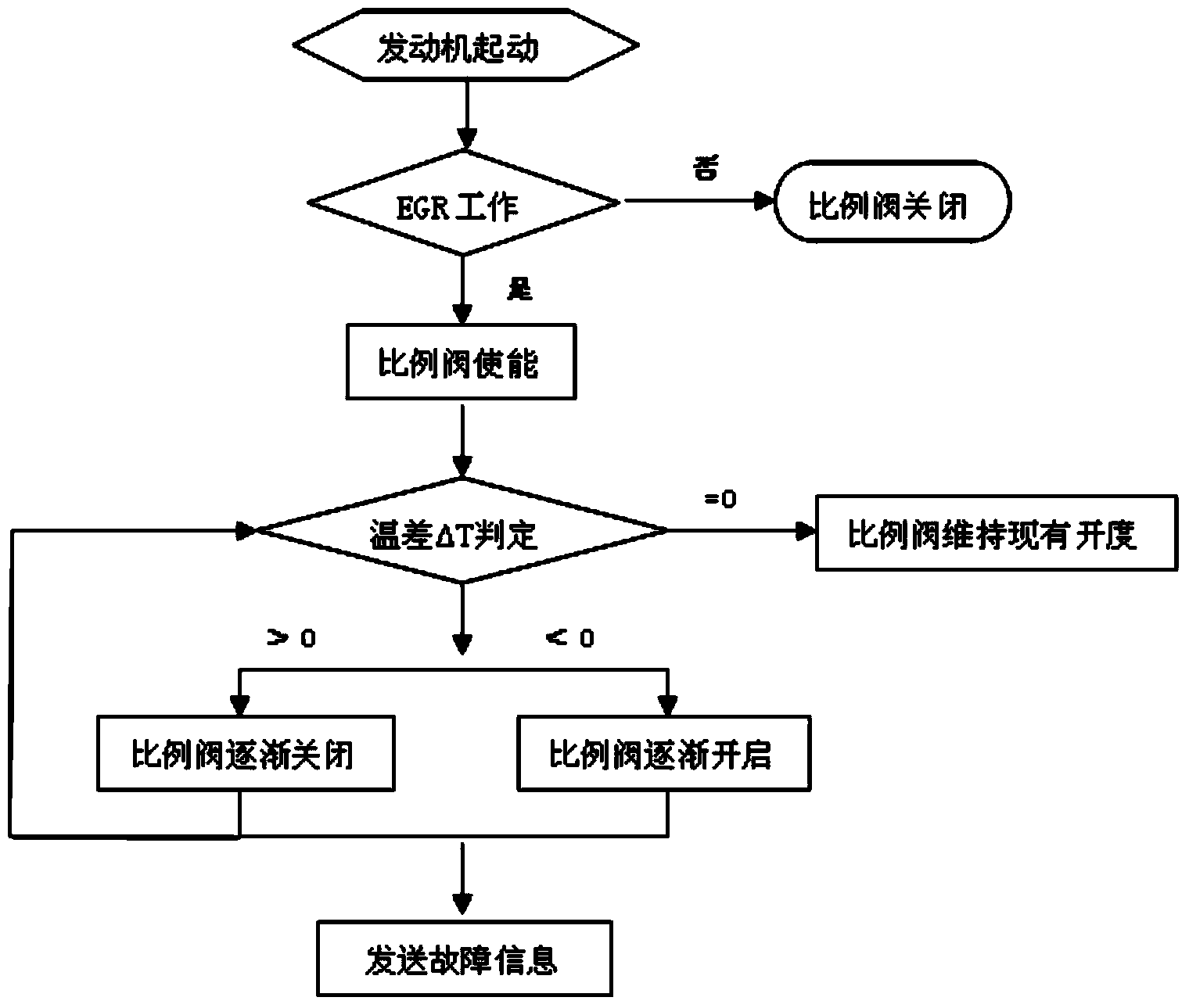
[0025] The engine EGR system of the present invention has a simple and reasonable structure, adopts a bypass pipeline with a proportional valve connected in parallel with the EGR cooler, and realizes waste gas bypass with different flow rates by adjusting the opening ratio of the proportional valve, so as to adjust the flow rate before entering the EGR valve....


PUM


Abstract

The invention discloses an engine EGR (Exhaust Gas Recirculation) system, comprising an EGR cooler, an EGR valve, a by-pass line and a temperature sensor, wherein the EGR valve is communicated with the gas outlet end of the EGR cooler; the by-pass line is connected with the EGR cooler in parallel; an exhaust gas flow control proportional valve which is connected with an ECU (Engine Control Unit) in a controlling way is mounted at the inlet of the by-pass line; the temperature sensor is arranged between the outlet of the by-pass line and the EGR valve and is taken as an input end used for collecting the valve inlet exhaust gas temperature of the EGR valve by the ECU. The engine EGR system is simple in structure; the by-pass line which is connected with the EGR cooler in parallel and is provided with the proportional valve is adopted; the temperature of the valve inlet exhaust gas entering the EGR valve is adjusted by adjusting the opening proportion of the proportional valve; the EGR valve inlet exhaust gas temperature is controllable under all operating working conditions of an engine; the EGR system is free of carbon deposition and gum deposit; therefore the temperature of the mixed gas entering an engine cylinder can be well controlled; the optimal states of engine performance and discharge are realized; the cooling efficiency of the EGR cooler is monitored in real time, so that the reliability of a product is ensured.

Description

technical field [0001] The invention relates to the field of engines, in particular to an engine EGR system. Background technique [0002] As the engine reduces NO x One of the main means of emission, EGR (Exhaust Gas Recirculation) technology is widely used in light vehicle engines. With the advancement of the automobile industry, EGR technology has made great progress, from vacuum-controlled pneumatic EGR valves to electric EGR valves driven by DC motors; from non-cooled EGR systems to cooled EGR systems with EGR coolers. Greatly promoted the successful application of EGR technology in the engine. [0003] However, with the increasingly stringent emission regulations, the engine's demand for EGR exhaust gas (that is, the EGR rate) is gradually increasing, and the stability and durability of the EGR system have become increasingly prominent. In an engine equipped with an EGR system, how to avoid problems such as carbon deposition and gelation caused by the long-term use ...

Claims


Application Information

Patent Timeline
Patent Type & Authority Applications(China)
IPC IPC(8): F02M25/07F02M26/05F02M26/28F02M26/33F02M26/49
CPCY02T10/121Y02T10/12
Inventor 李明星朱万冬王辉黎幸荣
Owner GUANGXI YUCHAI MASCH CO LTD
Why Eureka
Try Eureka