Automatic installation mechanism of tool bit

A technology of automatic installation and cutter head, which is applied in the direction of auxiliary devices, auxiliary welding equipment, welding/cutting auxiliary equipment, etc., and can solve the problems of cumbersome loading operations when stopping the machine

CN103551767AInactive Publication Date: 2014-02-05福建南安市华天机械有限公司
7 Cites 0 Cited by

Patent Information

Authority / Receiving Office
CN · China
Current Assignee / Owner
Publication Date
2014-02-05
Estimated Expiration
Not applicable · inactive patent

Smart Images

  • Figure 1
    Figure 1
  • Figure 2
    Figure 2
  • Figure 3
    Figure 3
Patent Text Reader

Abstract

The invention discloses an automatic installation mechanism of a tool bit. The automatic installation mechanism mainly comprises a base and a carrier plate, wherein a carrier plate groove and a tool bit groove, which form a T-shaped groove structure in a horizontal and vertical manner, are arranged in the base; the carrier plate groove is horizontally extended, and is provided with two free ends and a first knife outlet which is communicated with the tool bit groove, and one free end of the carrier plate groove is opened to form a second knife outlet; a knife push part is arranged in the tool bit groove, and the knife push part is connected with a first drive unit capable of driving the knife push part to move in the tool bit groove back and forth; the carrier plate is movably embedded into the carrier plate groove, a stepped knife placing position is arranged on one end of the carrier plate, and the carrier plate is connected with a second drive unit capable of driving the knife placing position to slide inside and outside the carrier plate groove back and forth. According to the automatic installation mechanism of the tool bit, simple, quick, stable and reliable automatic installation is realized, the automatic installation mechanism has the advantages of simple structure, simplicity in operation, stable and reliable installation and the like. The tool bit groove is further improved, so that the whole installation process is full-automatic quick streamlined operation.
Need to check novelty before this filing date? Find Prior Art

Description

technical field

[0001] The invention relates to a cutting head welding technology, in particular to a cutting head automatic installation mechanism applied to a cutting head welding machine. Background technique

[0002] The cutter head welding machine is a kind of welding equipment that welds the diamond cutter head on the substrate. Generally, it mainly includes a welding mechanism, a substrate clamping mechanism, a cutter head clamping mechanism and a cutter head lifting mechanism. When working, the substrate is clamped by the substrate clamping mechanism, the cutter head is clamped by the cutter head clamping mechanism, and the clamped cutter head is sent to dock with the substrate through the cutter head lifting mechanism, and finally the cutter head is connected to the substrate by the welding mechanism. The substrate is welded together. A piece of substrate is welded with multiple cutter heads (up to hundreds of them) around its periphery. The accuracy of the connect...

Examples

Embodiment Construction

[0035] The present case will be described in further detail below in conjunction with the accompanying drawings and specific embodiments.

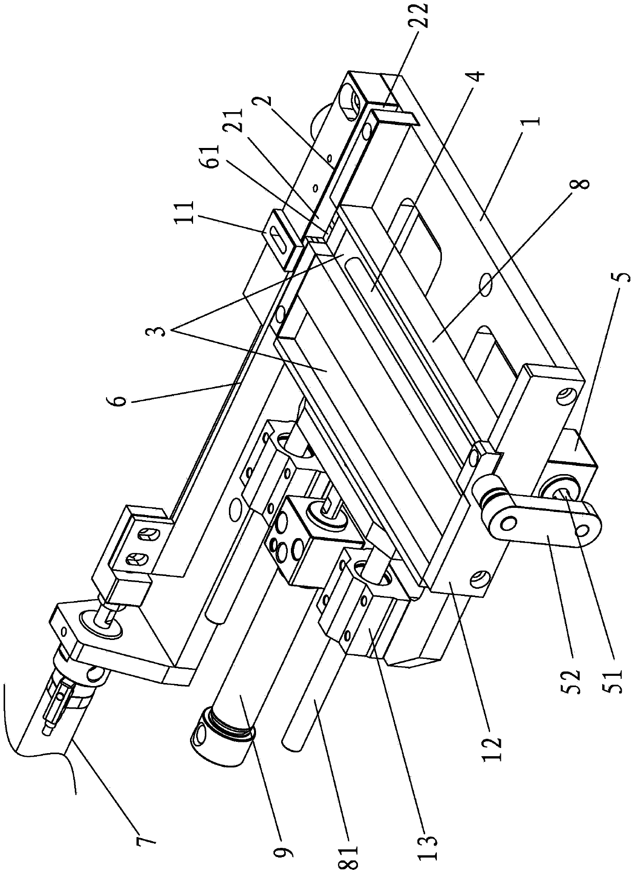
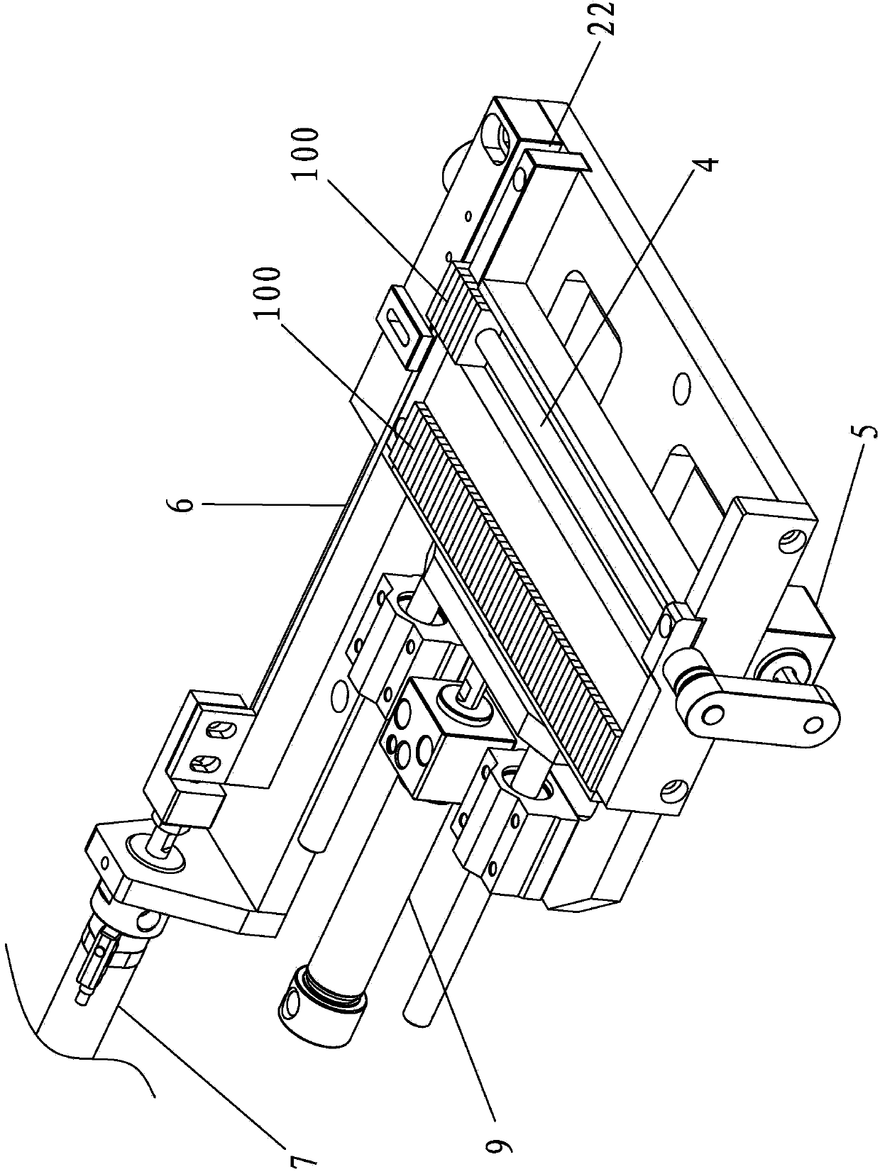
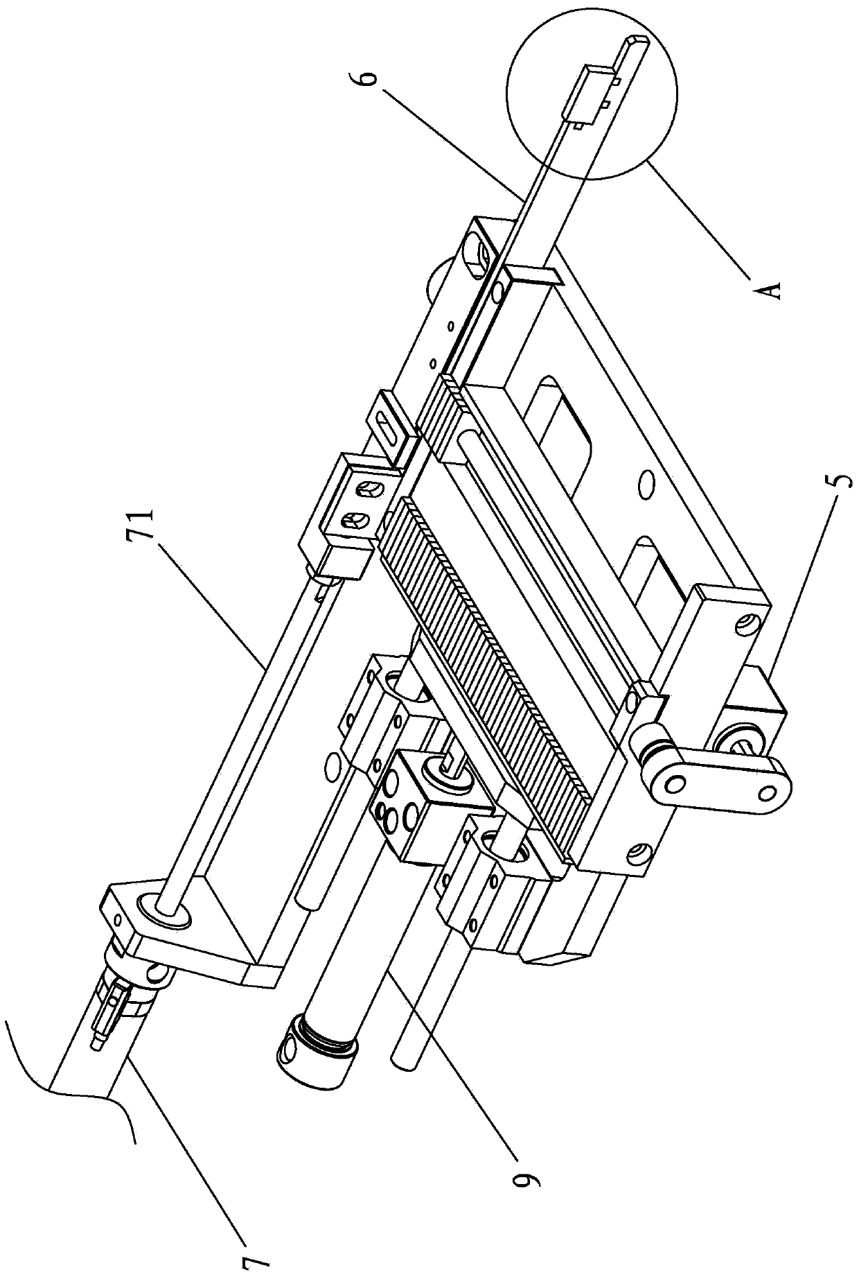
[0036] This case involves an automatic cutter head installation mechanism, see Figure 1-4 As shown, it mainly includes a base 1 , a conveying plate groove 2 , a knife head groove 3 , a pushing knife portion 4 and a conveying plate 6 .

[0037] The conveying plate groove 2 and the cutter head groove 3 shown are arranged on the base 1, and both of them extend horizontally and vertically to form a T-shaped groove structure. Concretely, conveying plate groove 2 extends laterally, and it has two free ends and the first knife outlet 21 that communicates with cutter head groove 3, and a free end of conveying plate groove 2 is open shape, is the second knife outlet 22 . The cutter head slot 3 has a free end and a connecting portion communicating with the first cutter outlet 21 . In the horizontal direction, the second knife outlet 22 is in the...