Manipulator storage cabinet

A technology of manipulators and storage cabinets, which is applied in the field of storage cabinets and can solve problems such as the inability to apply automatic manipulators

Pending Publication Date: 2018-01-05
镇江玄润电气设备有限公司
View PDF0 Cites 0 Cited by
  • Summary
  • Abstract
  • Description
  • Claims
  • Application Information

AI Technical Summary

Problems solved by technology

[0002] The manipulator is divided into two parts, the mobile base and the operating head; different operations require different operating heads, but there is only one mobile base, which needs to be moved to the storage cabinet to automatically find the required operating head and position it to complete the automatic installation; on the market The storage cabinet of the manipulator only has a storage function, and cannot be applied to the automatic taking of the manipulator, because in order to realize the automatic taking, it needs to be able to accurately locate and push the manipulator out of the storage room to facilitate the automatic installation of the manipulator. This invention solves these problems

Method used


Image

  • Manipulator storage cabinet

Examples


Embodiment Construction

[0017] The present invention will be specifically introduced below in conjunction with the accompanying drawings and specific embodiments.

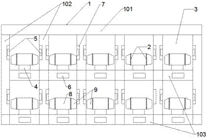
[0018] The manipulator storage cabinet includes: storage cabinet fixing rods 1, partitions fixed between the storage cabinet fixing rods 1, a storage room 3 formed between the partitions and storing the manipulator operation head, set in the storage room 3 and fixedly operated The manipulator fixing assembly at the rear end of the head pushes the manipulator out of the storage room 3 and is fixed to the pusher 4 at the rear end of the manipulator fixing assembly, and is arranged on the positioning assembly on the storage cabinet fixing rod 1 .

[0019] The storage cabinet fixed rod 1 is composed of: a push rod 101 arranged on the storage room 3 , a side bar 102 arranged on both sides of the storage room 3 , and a bottom bar 103 arranged under the storage room 3 . The positioning assembly consists of: a first induction block 5 arranged on ...


PUM


Abstract

The invention discloses a manipulator storage cabinet, comprising: storage cabinet fixing rods, partitions fixed between the storage cabinet fixing rods, a storage room formed between the partitions and storing the manipulator operation head, arranged in the storage room and The manipulator fixing component that fixes the rear end of the operating head, pushes the manipulator out of the storage room and fixes the pusher at the rear end of the manipulator fixing component, and the positioning component that is arranged on the fixing rod of the storage cabinet. The invention provides a storage cabinet for manipulators. The operating head is pushed out of the storage room through a pusher to facilitate the automatic installation of the manipulator; the manipulator fixing assembly is used to fix the operating head stably to ensure smooth automatic installation; The placement position of the operation head, and accurately find the installation part on the operation head to complete the precise installation.

Description

technical field [0001] The invention relates to production line auxiliary equipment, in particular to a storage cabinet. Background technique [0002] The manipulator is divided into two parts, the mobile base and the operating head; different operations require different operating heads, but there is only one mobile base, which needs to be moved to the storage cabinet to automatically find the required operating head and position it to complete the automatic installation; on the market The storage cabinet of the manipulator only has a storage function and cannot be applied to the automatic taking of the manipulator, because to realize the automatic taking, it needs to be able to accurately locate and push the manipulator out of the storage room to facilitate the automatic installation of the manipulator. The present invention solves these problems. Contents of the invention [0003] In order to solve the deficiencies of the prior art, the purpose of the present invention ...

Claims


Application Information

Patent Timeline
Patent Type & Authority Applications(China)
IPC IPC(8): B25J19/00
Inventor 高超张伟管鑫焱
Owner 镇江玄润电气设备有限公司
Why Eureka
Try Eureka