
Discharging and packaging device for printing paper roll

A paper roll and output slot technology, applied in the directions of packaging, transportation and packaging, single objects, etc., can solve the problems of low packaging efficiency and labor consumption, and achieve the effect of convenient automatic installation and convenient packaging operations.

Active Publication Date: 2020-01-17
台州金荣企业管理合伙企业(有限合伙)
View PDF6 Cites 0 Cited by
  • Summary
  • Abstract
  • Description
  • Claims
  • Application Information

AI Technical Summary

Problems solved by technology

However, during the packaging process of the existing paper tape roll, it is installed in a square carton. The packaging is mainly done by hand, which has low packaging efficiency and consumes a lot of manpower. Can you design a paper tape roll processing equipment? The connected packaging device can automatically install the finished products output by the paper tape roll processing equipment into the packaging box directly through the packaging device

Method used


Image

  • Discharging and packaging device for printing paper roll
  • Discharging and packaging device for printing paper roll
  • Discharging and packaging device for printing paper roll

Examples


Embodiment Construction

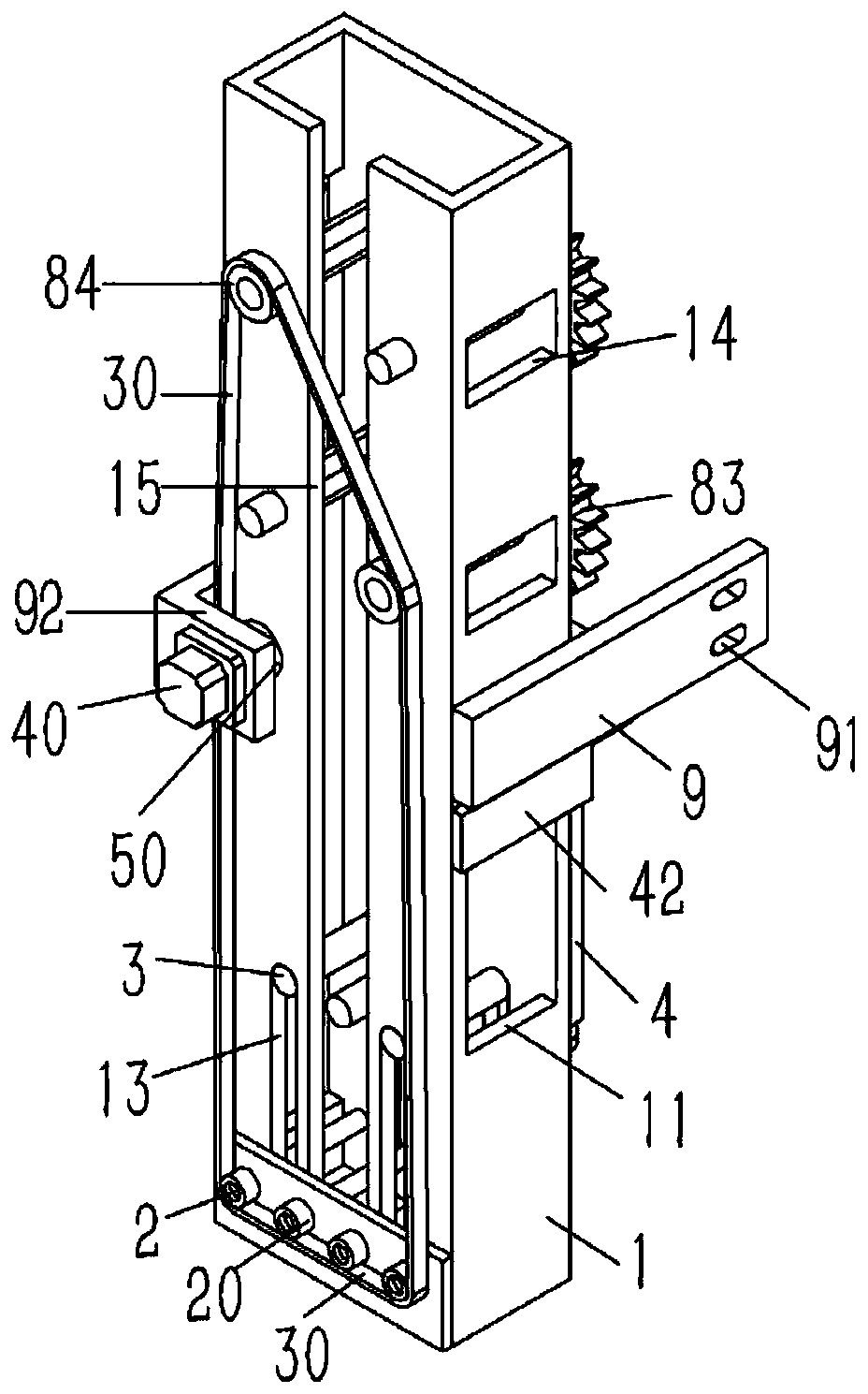
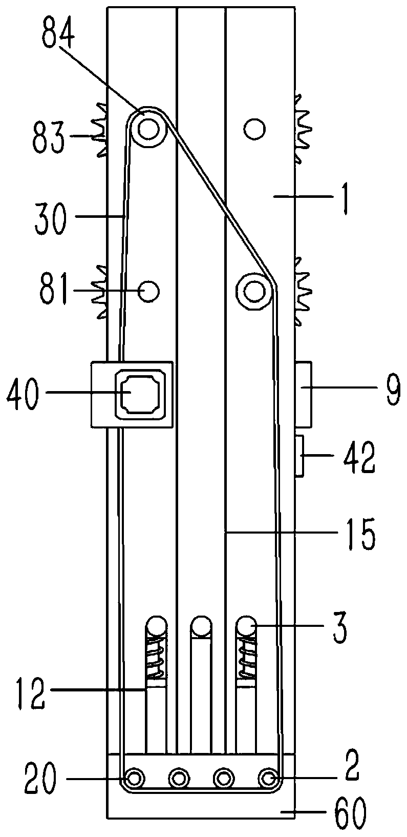
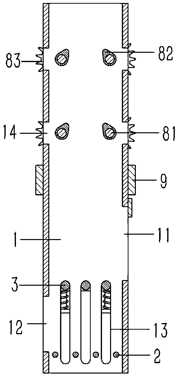
[0021] Example: see Figures 1 to 4 As shown, a discharge packaging device for printing paper rolls includes a rectangular and vertical output channel 1, the lower end of the output channel 1 is inserted with a number of longitudinal rollers 2, and the two ends of the rollers 2 are hinged On the output channel 1, the front end of the roller shaft 2 passes through the support plate 60 to insert and fix the first pulley 20, and the support plate 60 is fixed on the front end surface of the output channel 1, and the output between the roller shafts 2 A vertical guide groove 13 is formed on the front and rear end surfaces of the channel 1, and a longitudinal support rod 3 is inserted in the guide groove 13. The rear end of the support rod 3 is fixed on the slide plate 4, and the slide plate 4 is against the output On the rear end surface of the channel 1, a horizontal branch plate 41 is formed on the upper end of the slide plate 4, and a plurality of T-shaped guide rods 5 are inser...


PUM


Abstract

The invention discloses a discharging and packaging device for a printing paper roll. The discharging and packaging device includes a rectangular and vertical output groove channel, a plurality of longitudinal roll shafts are connected to the lower end of the output groove channel in an inserted mode, and the two ends of the roller shafts are hinged to the output groove channel; the front ends ofthe roll shafts penetrate through a supporting plate to be fixedly provided with first pulleys in inserted and sleeved modes, and the supporting plate is fixed on the front end surface of the output groove channel; vertical guide grooves are formed in the front end surface and the rear end surface, between the roll shafts, of the output groove channel, supporting rods are connected into the guidegrooves in an inserted mode, the rear ends of the supporting rod are fixed on a sliding plate, the sliding plate abuts against the rear end surface of the output groove channel, and a horizontal branch plate is formed at the upper end of the sliding plate; the branch plate is connected with a plurality of T-shaped guide rods in an inserted mode, the upper ends of the guide rods penetrate through the branch plate to be fixed to a fixed block, and the fixed block is fixed to the rear end surface of the output groove channel; and compression springs sleeve the guide rods in an inserted mode, andthe two ends of the compression springs are pressed against the lower ends of the guide rods and the branch plate correspondingly. The discharging and packaging device can be used for connecting production equipment of a paper tape roll, and the paper tape roll can be conveniently and automatically installed in a packaging box, so that the packaging operation of the printing paper roll is facilitated.

Description

technical field [0001] The present invention relates to the technical field of printing machinery, and more specifically relates to an output packaging device for printing paper rolls. Background technique [0002] At present, the bills printed for charging by supermarkets, taxis, etc. are slender paper strips, and the paper source of the bills comes from roll-shaped paper tape rolls, which are cut and rolled into shape by corresponding processing equipment. However, during the packaging process of the existing paper tape roll, it is installed in a square carton. The packaging is mainly done by hand, which has low packaging efficiency and consumes a lot of manpower. Can you design a paper tape roll processing equipment? The connected packaging device can automatically install the finished products output by the paper tape roll processing equipment into the packaging box directly through the packaging device. Contents of the invention [0003] The purpose of the present in...

Claims


Application Information

Patent Timeline
Patent Type & Authority Applications(China)
IPC IPC(8): B65B35/04B65B5/04
CPCB65B5/04B65B35/04
Inventor 彭小林
Owner 台州金荣企业管理合伙企业(有限合伙)
Learn More